HP Pavilion dm1-4400 HP Pavilion dm1 Entertainment PC Maintenance and Service - Page 64
Power connector cable
 |
View all HP Pavilion dm1-4400 manuals
Add to My Manuals
Save this manual to your list of manuals |
Page 64 highlights
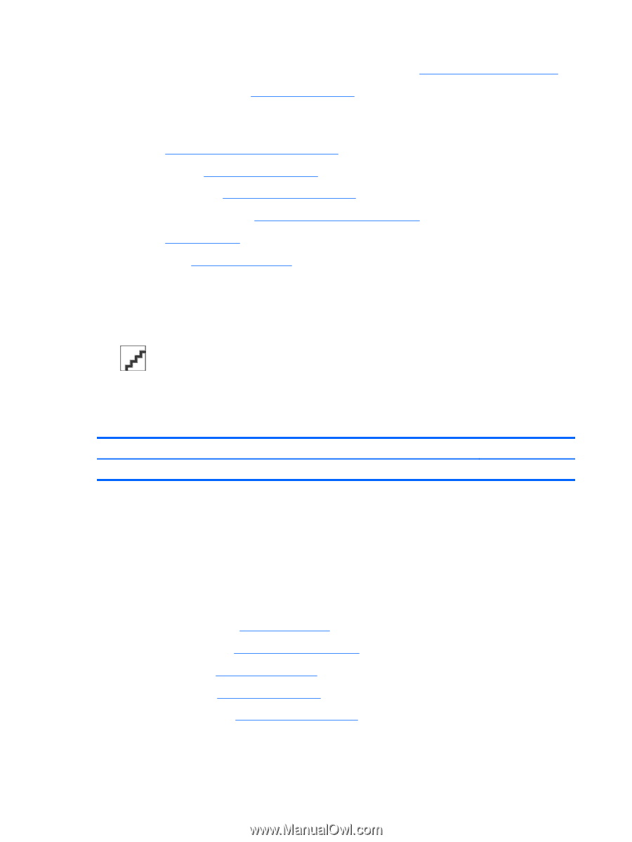
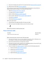
9. Disconnect the display panel cable from the system board (see Display assembly on page 49). 10. Remove the top cover (see Top cover on page 51). When replacing the system board, be sure that the following components are removed from the defective system board and installed on the replacement system board: ● SIM (see SIM (select models only) on page 37) ● RTC battery (see RTC battery on page 44) ● Memory module (see Memory module on page 46) ● Power connector cable (see Power connector cable on page 56) ● Fan (see Fan on page 58) ● Heat sink (see Heat sink on page 58) Remove the system board: 1. Lift the left side of the system board (1) until it rests at an angle. 2. Remove the system board (2) by sliding it up and to the left at an angle. Reverse this procedure to install the system board. Power connector cable Description Power connector cable (includes bracket) Spare part number 664995-001 Before removing the power connector cable, follow these steps: 1. Shut down the computer. If you are unsure whether the computer is off or in Hibernation, turn the computer on, and then shut it down through the operating system. 2. Disconnect all external devices connected to the computer. 3. Disconnect the power from the computer by first unplugging the power cord from the AC outlet and then unplugging the AC adapter from the computer. 4. Remove the battery (see Battery on page 37), and then remove the following components: a. Service cover (see WLAN module on page 40) b. Keyboard (see Keyboard on page 48) c. Top cover (see Top cover on page 51) d. System board (see System board on page 54) 56 Chapter 4 Removal and replacement procedures
-
 1
1 -
2
-
3
-
4
-
5
-
6
-
7
-
8
-
9
-
10
-
11
-
12
-
13
-
14
-
15
-
16
-
17
-
18
-
19
-
20
-
21
-
22
-
23
-
24
-
25
-
26
-
27
-
28
-
29
-
30
-
31
-
32
-
33
-
34
-
35
-
36
-
37
-
38
-
39
-
40
-
41
-
42
-
43
-
44
-
45
-
46
-
47
-
48
-
49
-
50
-
51
-
52
-
53
-
54
-
55
-
56
-
57
-
58
-
 59
59 -
 60
60 -
 61
61 -
 62
62 -
 63
63 -
 64
64 -
 65
65 -
 66
66 -
 67
67 -
 68
68 -
 69
69 -
70
-
71
-
72
-
73
-
74
-
75
-
76
-
77
-
78
-
79
-
80
-
81
-
82
-
83
-
84
-
85
-
86
-
87
-
88
-
89
-
90
-
91
-
92
-
93
-
94
-
95
-
96
-
97
-
98
 |
 |