HP Pavilion dv3 HP Pavilion dv3 Entertainment PC - Maintenance and Service Gui - Page 62
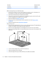
Remove the three Phillips PM2.0×4.0 screws, that secure the top cover to the computer in
 |
View all HP Pavilion dv3 manuals
Add to My Manuals
Save this manual to your list of manuals |
Page 62 highlights
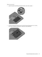
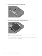
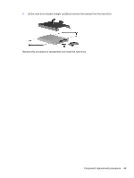
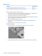
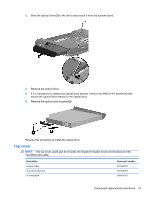
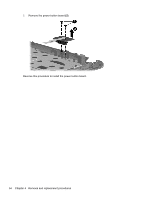
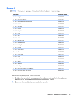
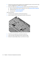
Description In shell white In Sonoma red Spare part number 606035-001 606034-001 Before removing the top cover, follow these steps: 1. Shut down the computer. If you are unsure whether the computer is off or in Hibernation, turn the computer on, and then shut it down through the operating system. 2. Disconnect all external devices connected to the computer. 3. Disconnect the power from the computer by first unplugging the power cord from the AC outlet and then unplugging the AC adapter from the computer. 4. Remove the battery (see Battery on page 38). 5. Remove the memory module/wireless module compartment cover (see Memory module on page 39). 6. Remove the optical drive (see Optical drive on page 50). Remove the top cover: 1. Remove the two rubber feet (1) from the rear corners of the base enclosure. The rubber feet are included in the Rubber Feet Kit, spare part number 599424-001. 2. Remove the nine Phillips PM2.5×7.0 screws (2) that secure the top cover to the computer. 3. Remove the three Phillips PM2.0×4.0 screws (3) that secure the top cover to the computer in the battery bay. 4. Turn the computer display-side up, with the front toward you. 5. Open the computer as far as it will open. 6. Lift the front edge of the top cover (1) until the top cover cables are accessible. 52 Chapter 4 Removal and replacement procedures
-
 1
1 -
2
-
3
-
4
-
5
-
6
-
7
-
8
-
9
-
10
-
11
-
12
-
13
-
14
-
15
-
16
-
17
-
18
-
19
-
20
-
21
-
22
-
23
-
24
-
25
-
26
-
27
-
28
-
29
-
30
-
31
-
32
-
33
-
34
-
35
-
36
-
37
-
38
-
39
-
40
-
41
-
42
-
43
-
44
-
45
-
46
-
47
-
48
-
49
-
50
-
51
-
52
-
53
-
54
-
55
-
56
-
 57
57 -
 58
58 -
 59
59 -
 60
60 -
 61
61 -
 62
62 -
 63
63 -
 64
64 -
 65
65 -
 66
66 -
 67
67 -
68
-
69
-
70
-
71
-
72
-
73
-
74
-
75
-
76
-
77
-
78
-
79
-
80
-
81
-
82
-
83
-
84
-
85
-
86
-
87
-
88
-
89
-
90
-
91
-
92
-
93
-
94
-
95
-
96
-
97
-
98
-
99
-
100
-
101
-
102
-
103
-
104
-
105
-
106
-
107
-
108
-
109
-
110
-
111
-
112
-
113
-
114
-
115
-
116
 |
 |
