HP Pavilion dv3 HP Pavilion dv3 Entertainment PC - Maintenance and Service Gui - Page 85
from the display panel cable., Disconnect the logo light cable
 |
View all HP Pavilion dv3 manuals
Add to My Manuals
Save this manual to your list of manuals |
Page 85 highlights
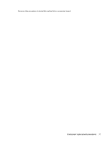
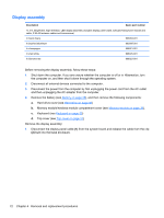
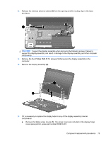
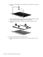
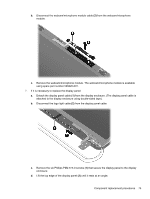
b. Disconnect the webcam/microphone module cable (2) from the webcam/microphone module. c. Remove the webcam/microphone module. The webcam/microphone module is available using spare part number 599420-001. 7. If it is necessary to replace the display panel: a. Detach the display panel cable (1) from the display enclosure. (The display panel cable is attached to the display enclosure using double-sided tape). b. Disconnect the logo light cable (2) from the display panel cable. c. Remove the six Phillips PM2.5×5.0 screws (1) that secure the display panel to the display enclosure. d. Lift the top edge of the display panel (2) until it rests at an angle. Component replacement procedures 75
-
 1
1 -
2
-
3
-
4
-
5
-
6
-
7
-
8
-
9
-
10
-
11
-
12
-
13
-
14
-
15
-
16
-
17
-
18
-
19
-
20
-
21
-
22
-
23
-
24
-
25
-
26
-
27
-
28
-
29
-
30
-
31
-
32
-
33
-
34
-
35
-
36
-
37
-
38
-
39
-
40
-
41
-
42
-
43
-
44
-
45
-
46
-
47
-
48
-
49
-
50
-
51
-
52
-
53
-
54
-
55
-
56
-
57
-
58
-
59
-
60
-
61
-
62
-
63
-
64
-
65
-
66
-
67
-
68
-
69
-
70
-
71
-
72
-
73
-
74
-
75
-
76
-
77
-
78
-
79
-
 80
80 -
 81
81 -
 82
82 -
 83
83 -
 84
84 -
 85
85 -
 86
86 -
 87
87 -
 88
88 -
 89
89 -
 90
90 -
91
-
92
-
93
-
94
-
95
-
96
-
97
-
98
-
99
-
100
-
101
-
102
-
103
-
104
-
105
-
106
-
107
-
108
-
109
-
110
-
111
-
112
-
113
-
114
-
115
-
116
 |
 |

b.
Disconnect the webcam/microphone module cable
(2)
from the webcam/microphone
module.
c.
Remove the webcam/microphone module. The webcam/microphone module is available
using spare part number 599420-001.
7.
If it is necessary to replace the display panel:
a.
Detach the display panel cable
(1)
from the display enclosure. (The display panel cable is
attached to the display enclosure using double-sided tape).
b.
Disconnect the logo light cable
(2)
from the display panel cable.
c.
Remove the six Phillips PM2.5×5.0 screws
(1)
that secure the display panel to the display
enclosure.
d.
Lift the top edge of the display panel
(2)
until it rests at an angle.
Component replacement procedures
75