HP Pavilion g4-2300 HP Pavilion g4 Notebook PC Maintenance and Service Guide - Page 81
Release the optical drive connector from the base enclosure by prying the clips
 |
View all HP Pavilion g4-2300 manuals
Add to My Manuals
Save this manual to your list of manuals |
Page 81 highlights
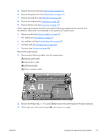
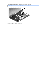
7. Remove the hard drive (see Hard drive on page 45). 8. Remove the keyboard (see Keyboard on page 52). 9. Remove the top cover (see Top cover on page 55). Remove the optical drive cable: 1. Disconnect the optical drive cable (1) from the system board. 2. Release the optical drive cable (2) from the clips built into the base enclosure. 3. Release the optical drive connector from the base enclosure by prying the clips (3) that secure the optical drive connector to the base enclosure. 4. Remove the optical drive cable from the base enclosure (4). Reverse this procedure to install the optical drive cable. ENWW Component replacement procedures 73
-
 1
1 -
2
-
3
-
4
-
5
-
6
-
7
-
8
-
9
-
10
-
11
-
12
-
13
-
14
-
15
-
16
-
17
-
18
-
19
-
20
-
21
-
22
-
23
-
24
-
25
-
26
-
27
-
28
-
29
-
30
-
31
-
32
-
33
-
34
-
35
-
36
-
37
-
38
-
39
-
40
-
41
-
42
-
43
-
44
-
45
-
46
-
47
-
48
-
49
-
50
-
51
-
52
-
53
-
54
-
55
-
56
-
57
-
58
-
59
-
60
-
61
-
62
-
63
-
64
-
65
-
66
-
67
-
68
-
69
-
70
-
71
-
72
-
73
-
74
-
75
-
 76
76 -
 77
77 -
 78
78 -
 79
79 -
 80
80 -
 81
81 -
 82
82 -
 83
83 -
 84
84 -
 85
85 -
 86
86 -
87
-
88
-
89
-
90
-
91
-
92
-
93
-
94
-
95
-
96
-
97
-
98
-
99
-
100
-
101
-
102
-
103
-
104
-
105
-
106
-
107
-
108
-
109
-
110
-
111
-
112
-
113
-
114
-
115
-
116
-
117
-
118
-
119
-
120
-
121
-
122
-
123
-
124
 |
 |

7.
Remove the hard drive (see
Hard drive
on page
45
).
8.
Remove the keyboard (see
Keyboard
on page
52
).
9.
Remove the top cover (see
Top cover
on page
55
).
Remove the optical drive cable:
1.
Disconnect the optical drive cable
(1)
from the system board.
2.
Release the optical drive cable
(2)
from the clips built into the base enclosure.
3.
Release the optical drive connector from the base enclosure by prying the clips
(3)
that secure
the optical drive connector to the base enclosure.
4.
Remove the optical drive cable from the base enclosure
(4)
.
Reverse this procedure to install the optical drive cable.
ENWW
Component replacement procedures
73