HP Pavilion g4-2300 HP Pavilion g4 Notebook PC Maintenance and Service Guide - Page 83
Power connector, Remove the power connector
 |
View all HP Pavilion g4-2300 manuals
Add to My Manuals
Save this manual to your list of manuals |
Page 83 highlights
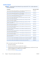
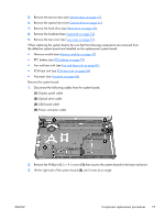
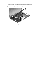
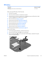
Reverse this procedure to install the USB board. Power connector Description Power connector (includes cable) Spare part number 680548-001 Before removing the power connector, follow these steps: 1. Shut down the computer. 2. Disconnect all external devices connected to the computer. 3. Disconnect the power from the computer by first unplugging the power cord from the AC outlet and then unplugging the AC adapter from the computer. 4. Remove the battery (see Battery on page 40). 5. Remove the service door (see Service door on page 41). 6. Remove the optical drive (see Optical drive on page 42). 7. Remove the hard drive (see Hard drive on page 45). 8. Remove the keyboard (see Keyboard on page 52). 9. Remove the top cover (see Top cover on page 55). Remove the power connector: 1. Disconnect the power connector cable (1) from the system board. 2. Remove the power connector from the base enclosure (2). Reverse this procedure to install the power connector. ENWW Component replacement procedures 75
-
 1
1 -
2
-
3
-
4
-
5
-
6
-
7
-
8
-
9
-
10
-
11
-
12
-
13
-
14
-
15
-
16
-
17
-
18
-
19
-
20
-
21
-
22
-
23
-
24
-
25
-
26
-
27
-
28
-
29
-
30
-
31
-
32
-
33
-
34
-
35
-
36
-
37
-
38
-
39
-
40
-
41
-
42
-
43
-
44
-
45
-
46
-
47
-
48
-
49
-
50
-
51
-
52
-
53
-
54
-
55
-
56
-
57
-
58
-
59
-
60
-
61
-
62
-
63
-
64
-
65
-
66
-
67
-
68
-
69
-
70
-
71
-
72
-
73
-
74
-
75
-
76
-
77
-
 78
78 -
 79
79 -
 80
80 -
 81
81 -
 82
82 -
 83
83 -
 84
84 -
 85
85 -
 86
86 -
 87
87 -
 88
88 -
89
-
90
-
91
-
92
-
93
-
94
-
95
-
96
-
97
-
98
-
99
-
100
-
101
-
102
-
103
-
104
-
105
-
106
-
107
-
108
-
109
-
110
-
111
-
112
-
113
-
114
-
115
-
116
-
117
-
118
-
119
-
120
-
121
-
122
-
123
-
124
 |
 |
