HP Pavilion g4-2300 HP Pavilion g4 Notebook PC Maintenance and Service Guide - Page 85
Remove the Phillips M2.5 × 4.5 screw, USB board cable
 |
View all HP Pavilion g4-2300 manuals
Add to My Manuals
Save this manual to your list of manuals |
Page 85 highlights
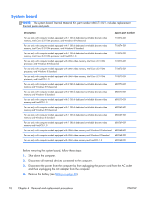
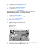
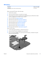
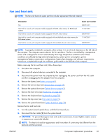
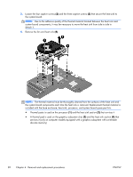
5. Remove the service door (see Service door on page 41). 6. Remove the optical drive (see Optical drive on page 42). 7. Remove the hard drive (see Hard drive on page 45). 8. Remove the keyboard (see Keyboard on page 52). 9. Remove the top cover (see Top cover on page 55). When replacing the system board, be sure that the following components are removed from the defective system board and installed on the replacement system board: ● Memory module (see Memory module on page 47) ● RTC battery (see RTC battery on page 79) ● Fan and heat sink (see Fan and heat sink on page 81). ● PCH heat sink (see PCH heat sink on page 84) ● Processor (see Processor on page 86) Remove the system board: 1. Disconnect the following cables from the system board: (1) Display panel cable (2) Optical drive cable (3) USB board cable (4) Power connector cable 2. Remove the Phillips M2.5 × 4.5 screw (1) that secures the system board to the base enclosure. 3. Lift the right side of the system board (2) until it rests at an angle. ENWW Component replacement procedures 77
-
 1
1 -
2
-
3
-
4
-
5
-
6
-
7
-
8
-
9
-
10
-
11
-
12
-
13
-
14
-
15
-
16
-
17
-
18
-
19
-
20
-
21
-
22
-
23
-
24
-
25
-
26
-
27
-
28
-
29
-
30
-
31
-
32
-
33
-
34
-
35
-
36
-
37
-
38
-
39
-
40
-
41
-
42
-
43
-
44
-
45
-
46
-
47
-
48
-
49
-
50
-
51
-
52
-
53
-
54
-
55
-
56
-
57
-
58
-
59
-
60
-
61
-
62
-
63
-
64
-
65
-
66
-
67
-
68
-
69
-
70
-
71
-
72
-
73
-
74
-
75
-
76
-
77
-
78
-
79
-
 80
80 -
 81
81 -
 82
82 -
 83
83 -
 84
84 -
 85
85 -
 86
86 -
 87
87 -
 88
88 -
 89
89 -
 90
90 -
91
-
92
-
93
-
94
-
95
-
96
-
97
-
98
-
99
-
100
-
101
-
102
-
103
-
104
-
105
-
106
-
107
-
108
-
109
-
110
-
111
-
112
-
113
-
114
-
115
-
116
-
117
-
118
-
119
-
120
-
121
-
122
-
123
-
124
 |
 |
