HP Pavilion g6-2300 HP Pavilion g6 Notebook PC Maintenance and Service Guide - Page 82
System board
 |
View all HP Pavilion g6-2300 manuals
Add to My Manuals
Save this manual to your list of manuals |
Page 82 highlights
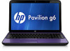
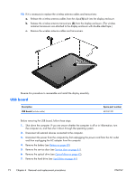
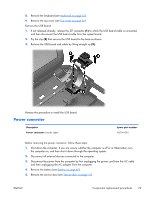
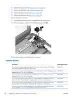
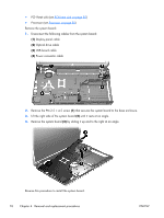
6. Remove the optical drive (see Optical drive on page 42). 7. Remove the hard drive (see Hard drive on page 44). 8. Remove the keyboard (see Keyboard on page 51). 9. Remove the top cover (see Top cover on page 56). Remove the power connector: 1. Disconnect the power connector cable (1) from the system board. 2. Remove the power connector from the the base enclosure (2). Reverse this procedure to install the power connector. System board Description Spare part number For use only with computer models equipped with UMA video memory, Windows 8 Professional, and a supported AMD A10, A8, A6, or A4 processor 683029-601 For use only with computer models equipped with UMA video memory, Windows 8 Standard, and a 683029-501 supported AMD A10, A8, A6, or A4 processor For use only with computer models equipped with UMA video memory, FreeDOS 1.0, and a supported AMD A10, A8, A6, or A4 processor 683029-001 For use only with computer models equipped with 1 GB of dedicated switchable discrete video memory, Windows 8 Professional, and a supported AMD A10, A8, A6, or A4 processor 683030-601 For use only with computer models equipped with 1 GB of dedicated switchable discrete video memory. Windows 8 Standard, and a supported AMD A10, A8, A6, or A4 processor 683030-501 For use only with computer models equipped with 1 GB of dedicated switchable discrete video memory, FreeDOS 1.0, and a supported AMD A10, A8, A6, or A4 processor 683030-001 74 Chapter 4 Removal and replacement procedures ENWW
-
 1
1 -
2
-
3
-
4
-
5
-
6
-
7
-
8
-
9
-
10
-
11
-
12
-
13
-
14
-
15
-
16
-
17
-
18
-
19
-
20
-
21
-
22
-
23
-
24
-
25
-
26
-
27
-
28
-
29
-
30
-
31
-
32
-
33
-
34
-
35
-
36
-
37
-
38
-
39
-
40
-
41
-
42
-
43
-
44
-
45
-
46
-
47
-
48
-
49
-
50
-
51
-
52
-
53
-
54
-
55
-
56
-
57
-
58
-
59
-
60
-
61
-
62
-
63
-
64
-
65
-
66
-
67
-
68
-
69
-
70
-
71
-
72
-
73
-
74
-
75
-
76
-
 77
77 -
 78
78 -
 79
79 -
 80
80 -
 81
81 -
 82
82 -
 83
83 -
 84
84 -
 85
85 -
 86
86 -
 87
87 -
88
-
89
-
90
-
91
-
92
-
93
-
94
-
95
-
96
-
97
-
98
-
99
-
100
-
101
-
102
-
103
-
104
-
105
-
106
-
107
-
108
-
109
-
110
-
111
-
112
-
113
-
114
-
115
-
116
-
117
-
118
-
119
-
120
-
121
-
122
-
123
-
124
 |
 |
