HP Pavilion g6-2300 HP Pavilion g6 Notebook PC Maintenance and Service Guide - Page 84
Lift the right side of the system board, Remove the PM 2.5 × 4.5 screw
 |
View all HP Pavilion g6-2300 manuals
Add to My Manuals
Save this manual to your list of manuals |
Page 84 highlights
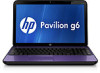
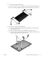
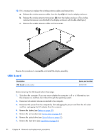
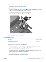
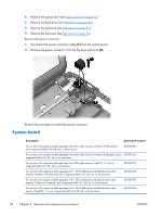
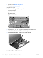
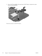
● PCH heat sink (see PCH heat sink on page 82) ● Processor (see Processor on page 83) Remove the system board: 1. Disconnect the following cables from the system board: (1) Display panel cable (2) Optical drive cable (3) USB board cable (4) Power connector cable 2. Remove the PM 2.5 × 4.5 screw (1) that secures the system board to the base enclosure. 3. Lift the right side of the system board (2) until it rests at an angle. 4. Remove the system board (3) by sliding it up and to the right at an angle. Reverse this procedure to install the system board. 76 Chapter 4 Removal and replacement procedures ENWW
-
 1
1 -
2
-
3
-
4
-
5
-
6
-
7
-
8
-
9
-
10
-
11
-
12
-
13
-
14
-
15
-
16
-
17
-
18
-
19
-
20
-
21
-
22
-
23
-
24
-
25
-
26
-
27
-
28
-
29
-
30
-
31
-
32
-
33
-
34
-
35
-
36
-
37
-
38
-
39
-
40
-
41
-
42
-
43
-
44
-
45
-
46
-
47
-
48
-
49
-
50
-
51
-
52
-
53
-
54
-
55
-
56
-
57
-
58
-
59
-
60
-
61
-
62
-
63
-
64
-
65
-
66
-
67
-
68
-
69
-
70
-
71
-
72
-
73
-
74
-
75
-
76
-
77
-
78
-
 79
79 -
 80
80 -
 81
81 -
 82
82 -
 83
83 -
 84
84 -
 85
85 -
 86
86 -
 87
87 -
 88
88 -
 89
89 -
90
-
91
-
92
-
93
-
94
-
95
-
96
-
97
-
98
-
99
-
100
-
101
-
102
-
103
-
104
-
105
-
106
-
107
-
108
-
109
-
110
-
111
-
112
-
113
-
114
-
115
-
116
-
117
-
118
-
119
-
120
-
121
-
122
-
123
-
124
 |
 |

●
PCH heat sink (see
PCH heat sink
on page
82
)
●
Processor (see
Processor
on page
83
)
Remove the system board:
1.
Disconnect the following cables from the system board:
(1)
Display panel cable
(2)
Optical drive cable
(3)
USB board cable
(4)
Power connector cable
2.
Remove the PM 2.5 × 4.5 screw
(1)
that secures the system board to the base enclosure.
3.
Lift the right side of the system board
(2)
until it rests at an angle.
4.
Remove the system board
(3)
by sliding it up and to the right at an angle.
Reverse this procedure to install the system board.
76
Chapter 4
Removal and replacement procedures
ENWW