HP Pavilion g6-2300 HP Pavilion g6 Notebook PC Maintenance and Service Guide - Page 83
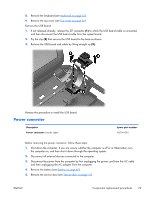
Remove the hard drive see, Remove the keyboard see
 |
View all HP Pavilion g6-2300 manuals
Add to My Manuals
Save this manual to your list of manuals |
Page 83 highlights
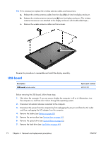
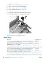
Description For use only with computer models equipped with 2 GB of dedicated switchable discrete video memory. Windows 8 Professional, and a supported AMD A10, A8, A6, or A4 processor For use only with computer models equipped with 2 GB of dedicated switchable discrete video memory. Windows 8 Standard, and a supported AMD A10, A8, A6, or A4 processor For use only with computer models equipped with 2 GB of dedicated switchable discrete video memory, FreeDOS 1.0, and a supported AMD A10, A8, A6, or A4 processor For use only with computer models equipped with AMD E2-1800 processor and Windows 8 Professional For use only with computer models equipped with AMD E2-1800 processor and Windows 8 Standard For use only with computer models equipped with AMD E2-1800 processor and FreeDOS 1.0 For use only with computer models equipped with AMD E2-2000 processor and Windows 8 Professional For use only with computer models equipped with AMD E2-2000 processor and Windows 8 Standard For use only with computer models equipped with AMD E2-2000 processor and FreeDOS 1.0 System board thermal pad kit (includes replacement thermal material) Spare part number 683031-601 683031-501 683031-001 697230-601 697230-501 697230-001 710875-601 710875-501 710875-001 680571-001 Before removing the system board, follow these steps: 1. Shut down the computer. If you are unsure whether the computer is off or in Hibernation, turn the computer on, and then shut it down through the operating system. 2. Disconnect all external devices connected to the computer. 3. Disconnect the power from the computer by first unplugging the power cord from the AC outlet and then unplugging the AC adapter from the computer. 4. Remove the battery (see Battery on page 40). 5. Remove the service door (see Service door on page 41). 6. Remove the optical drive (see Optical drive on page 42). 7. Remove the hard drive (see Hard drive on page 44). 8. Remove the keyboard (see Keyboard on page 51). 9. Remove the top cover (see Top cover on page 56). When replacing the system board, be sure that the following components are removed from the defective system board and installed on the replacement system board: ● Memory module (see Memory module on page 46) ● RTC battery (see RTC battery on page 77) ● Fan and heat sink (see Fan and heat sink on page 79) ENWW Component replacement procedures 75
-
 1
1 -
2
-
3
-
4
-
5
-
6
-
7
-
8
-
9
-
10
-
11
-
12
-
13
-
14
-
15
-
16
-
17
-
18
-
19
-
20
-
21
-
22
-
23
-
24
-
25
-
26
-
27
-
28
-
29
-
30
-
31
-
32
-
33
-
34
-
35
-
36
-
37
-
38
-
39
-
40
-
41
-
42
-
43
-
44
-
45
-
46
-
47
-
48
-
49
-
50
-
51
-
52
-
53
-
54
-
55
-
56
-
57
-
58
-
59
-
60
-
61
-
62
-
63
-
64
-
65
-
66
-
67
-
68
-
69
-
70
-
71
-
72
-
73
-
74
-
75
-
76
-
77
-
 78
78 -
 79
79 -
 80
80 -
 81
81 -
 82
82 -
 83
83 -
 84
84 -
 85
85 -
 86
86 -
 87
87 -
 88
88 -
89
-
90
-
91
-
92
-
93
-
94
-
95
-
96
-
97
-
98
-
99
-
100
-
101
-
102
-
103
-
104
-
105
-
106
-
107
-
108
-
109
-
110
-
111
-
112
-
113
-
114
-
115
-
116
-
117
-
118
-
119
-
120
-
121
-
122
-
123
-
124
 |
 |
