HP Pavilion tx1100 HP Pavilion tx1000 Entertainment PC - Maintenance and Servi - Page 71
System board, Display assembly see
 |
View all HP Pavilion tx1100 manuals
Add to My Manuals
Save this manual to your list of manuals |
Page 71 highlights
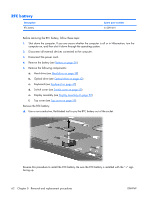
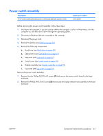
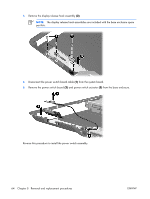
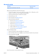
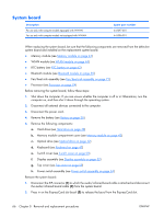
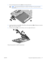
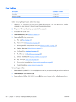
System board Description For use only with computer models equipped with WWAN For use only with computer models not equipped with WWAN Spare part number 441097-001 441096-001 When replacing the system board, be sure that the following components are removed from the defective system board and installed on the replacement system board: ● Memory module (see Memory module on page 43) ● WLAN module (see WLAN module on page 44) ● RTC battery (see RTC battery on page 62) ● Bluetooth module (see Bluetooth module on page 65) ● Fan/heat sink assembly (see Fan/heat sink assembly on page 71) ● Processor (see Processor on page 74) Before removing the system board, follow these steps: 1. Shut down the computer. If you are unsure whether the computer is off or in Hibernation, turn the computer on, and then shut it down through the operating system. 2. Disconnect all external devices connected to the computer. 3. Disconnect the power cord. 4. Remove the battery (see Battery on page 36). 5. Remove the following components: a. Hard drive (see Hard drive on page 38) b. Memory module compartment cover (see Memory module on page 43) c. Optical drive (see Optical drive on page 42) d. Keyboard (see Keyboard on page 47) e. Switch cover (see Switch cover on page 50) f. Display assembly (see Display assembly on page 52) g. Top cover (see Top cover on page 59) h. Power switch assembly (see Power switch assembly on page 63) Remove the system board: 1. Disconnect the ZIF connector (1) to which the audio/infrared board cable is attached and disconnect the audio/infrared board cable (2) from the system board. 2. Press in on the ExpressCard slot bezel (3) to release the bezel from the ExpressCard slot. 66 Chapter 5 Removal and replacement procedures ENWW
-
 1
1 -
2
-
3
-
4
-
5
-
6
-
7
-
8
-
9
-
10
-
11
-
12
-
13
-
14
-
15
-
16
-
17
-
18
-
19
-
20
-
21
-
22
-
23
-
24
-
25
-
26
-
27
-
28
-
29
-
30
-
31
-
32
-
33
-
34
-
35
-
36
-
37
-
38
-
39
-
40
-
41
-
42
-
43
-
44
-
45
-
46
-
47
-
48
-
49
-
50
-
51
-
52
-
53
-
54
-
55
-
56
-
57
-
58
-
59
-
60
-
61
-
62
-
63
-
64
-
65
-
 66
66 -
 67
67 -
 68
68 -
 69
69 -
 70
70 -
 71
71 -
 72
72 -
 73
73 -
 74
74 -
 75
75 -
 76
76 -
77
-
78
-
79
-
80
-
81
-
82
-
83
-
84
-
85
-
86
-
87
-
88
-
89
-
90
-
91
-
92
-
93
-
94
-
95
-
96
-
97
-
98
-
99
-
100
-
101
-
102
-
103
-
104
-
105
-
106
-
107
-
108
-
109
-
110
-
111
-
112
-
113
-
114
-
115
-
116
-
117
-
118
-
119
-
120
-
121
-
122
-
123
-
124
-
125
-
126
-
127
-
128
-
129
-
130
-
131
 |
 |
