HP Presario CQ57-200 Compaq Presario CQ57 Notebook PC - Maintenance and Servic - Page 45
Remove the Phillips PM2.5×6.0 screw
 |
View all HP Presario CQ57-200 manuals
Add to My Manuals
Save this manual to your list of manuals |
Page 45 highlights
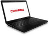
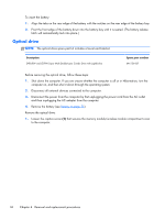
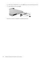
2. Lift the rear edge of the memory module/wireless module compartment cover (2) up and forward until it rests at an angle. 3. Remove the memory module/wireless module compartment cover. The memory module/wireless module compartment cover is available in the Plastics Kit, spare part number 646131-001. 4. Remove the Phillips PM2.5×6.0 screw (1) that secures the optical drive to the computer. 5. Insert an unbent paper clip or similar thin tool into the optical drive tab access (2) to release the optical drive tray from the optical drive. 6. Remove the optical drive (2) by sliding it out of the optical drive bay. 7. If it is necessary to replace the optical drive bracket, position the optical drive with the rear panel toward you. Component replacement procedures 37
-
 1
1 -
2
-
3
-
4
-
5
-
6
-
7
-
8
-
9
-
10
-
11
-
12
-
13
-
14
-
15
-
16
-
17
-
18
-
19
-
20
-
21
-
22
-
23
-
24
-
25
-
26
-
27
-
28
-
29
-
30
-
31
-
32
-
33
-
34
-
35
-
36
-
37
-
38
-
39
-
 40
40 -
 41
41 -
 42
42 -
 43
43 -
 44
44 -
 45
45 -
 46
46 -
 47
47 -
 48
48 -
 49
49 -
 50
50 -
51
-
52
-
53
-
54
-
55
-
56
-
57
-
58
-
59
-
60
-
61
-
62
-
63
-
64
-
65
-
66
-
67
-
68
-
69
-
70
-
71
-
72
-
73
-
74
-
75
-
76
-
77
-
78
-
79
-
80
-
81
-
82
-
83
-
84
-
85
-
86
-
87
-
88
-
89
-
90
-
91
-
92
-
93
-
94
-
95
-
96
-
97
-
98
-
99
-
100
-
101
-
102
-
103
-
104
-
105
-
106
-
107
-
108
-
109
-
110
-
111
-
112
 |
 |
