HP Presario CQ57-200 Compaq Presario CQ57 Notebook PC - Maintenance and Servic - Page 81
Remove the fan and heat sink, Remove the fan/heat sink assembly
 |
View all HP Presario CQ57-200 manuals
Add to My Manuals
Save this manual to your list of manuals |
Page 81 highlights
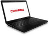
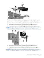
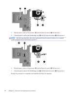
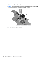
Remove the fan/heat sink assembly: 1. Disconnect the fan cable from the system board. 2. Turn the system board upside down, with the front toward you. 3. Loosen the captive screws (1) that secure the fan/heat sink assembly to the system board. NOTE: The number of screws used to secure the fan/heat sink assembly to the system board varies by computer model. NOTE: Due to the adhesive quality of the thermal material located between the heat sink and system board components, it may be necessary to move the heat sink from side to side to detach it. 4. Remove the fan and heat sink (2). NOTE: The following illustration shows the fan/heat sink assembly removal process on a computer model equipped with an Intel processor, the Intel HM65 or HM55 chipset, and a graphics subsystem with discrete memory. Component replacement procedures 73
-
 1
1 -
2
-
3
-
4
-
5
-
6
-
7
-
8
-
9
-
10
-
11
-
12
-
13
-
14
-
15
-
16
-
17
-
18
-
19
-
20
-
21
-
22
-
23
-
24
-
25
-
26
-
27
-
28
-
29
-
30
-
31
-
32
-
33
-
34
-
35
-
36
-
37
-
38
-
39
-
40
-
41
-
42
-
43
-
44
-
45
-
46
-
47
-
48
-
49
-
50
-
51
-
52
-
53
-
54
-
55
-
56
-
57
-
58
-
59
-
60
-
61
-
62
-
63
-
64
-
65
-
66
-
67
-
68
-
69
-
70
-
71
-
72
-
73
-
74
-
75
-
 76
76 -
 77
77 -
 78
78 -
 79
79 -
 80
80 -
 81
81 -
 82
82 -
 83
83 -
 84
84 -
 85
85 -
 86
86 -
87
-
88
-
89
-
90
-
91
-
92
-
93
-
94
-
95
-
96
-
97
-
98
-
99
-
100
-
101
-
102
-
103
-
104
-
105
-
106
-
107
-
108
-
109
-
110
-
111
-
112
 |
 |
