HP Presario CQ57-200 Compaq Presario CQ57 Notebook PC - Maintenance and Servic - Page 68
Display assembly, Disconnect the display panel cable
 |
View all HP Presario CQ57-200 manuals
Add to My Manuals
Save this manual to your list of manuals |
Page 68 highlights
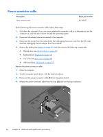
Display assembly Description Spare part number 15.6-in, HD, LED, BrightView display assembly (includes microphone and wireless antenna transceivers and cables) Equipped with webcam 645095-001 Not equipped with webcam 645094-001 Before removing the display assembly, follow these steps: 1. Shut down the computer. If you are unsure whether the computer is off or in Hibernation, turn the computer on, and then shut it down through the operating system. 2. Disconnect all external devices connected to the computer. 3. Disconnect the power from the computer by first unplugging the power cord from the AC outlet and then unplugging the AC adapter from the computer. 4. Remove the battery (see Battery on page 35), and then remove the following components: ● Optical drive (see Optical drive on page 36) ● WLAN module (see WLAN module on page 39) ● Keyboard (see Keyboard on page 45) ● Top cover (see Top cover on page 48) ● USB board (see USB board on page 55) ● Power connector cable (see Power connector cable on page 56) Remove the display assembly: 1. Disconnect the display panel cable (1) from the system board. 2. Release the wireless antenna cables from the clips (2) built into the base enclosure. CAUTION: Support the display assembly when removing the following screws. Failure to support the display assembly can result in damage to the display assembly and other computer components. 3. Remove the four Phillips PM2.5×6.0 screws (3) that secure the display assembly to the computer. 60 Chapter 4 Removal and replacement procedures
-
 1
1 -
2
-
3
-
4
-
5
-
6
-
7
-
8
-
9
-
10
-
11
-
12
-
13
-
14
-
15
-
16
-
17
-
18
-
19
-
20
-
21
-
22
-
23
-
24
-
25
-
26
-
27
-
28
-
29
-
30
-
31
-
32
-
33
-
34
-
35
-
36
-
37
-
38
-
39
-
40
-
41
-
42
-
43
-
44
-
45
-
46
-
47
-
48
-
49
-
50
-
51
-
52
-
53
-
54
-
55
-
56
-
57
-
58
-
59
-
60
-
61
-
62
-
 63
63 -
 64
64 -
 65
65 -
 66
66 -
 67
67 -
 68
68 -
 69
69 -
 70
70 -
 71
71 -
 72
72 -
 73
73 -
74
-
75
-
76
-
77
-
78
-
79
-
80
-
81
-
82
-
83
-
84
-
85
-
86
-
87
-
88
-
89
-
90
-
91
-
92
-
93
-
94
-
95
-
96
-
97
-
98
-
99
-
100
-
101
-
102
-
103
-
104
-
105
-
106
-
107
-
108
-
109
-
110
-
111
-
112
 |
 |
