HP Presario V6600 Compaq Presario V6500, V6600, and V6700 Notebook PCs - Maint - Page 52
Computer feet, Memory module, Remove the battery see
 |
View all HP Presario V6600 manuals
Add to My Manuals
Save this manual to your list of manuals |
Page 52 highlights
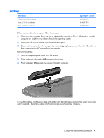
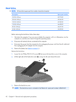
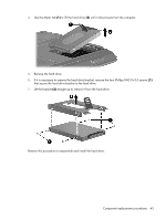
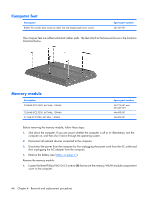
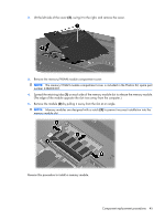
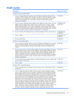
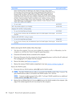
Computer feet Description Rubber Kit (includes base enclosure rubber feet and display bezel screw covers) Spare part number 431431-001 The computer feet are adhesive-backed rubber pads. The feet attach to the base enclosure in the locations illustrated below. Memory module Description 2048-MB (PC2-5300, 667-MHz, 1-DIMM) 1024-MB (PC2-5300, 667-MHz, 1-DIMM) 512-MB (PC2-5300, 667-MHz, 1-DIMM) Spare part number 453774-001 and 457437-001 446495-001 446494-001 Before removing the memory module, follow these steps: 1. Shut down the computer. If you are unsure whether the computer is off or in Hibernation, turn the computer on, and then shut it down through the operating system. 2. Disconnect all external devices connected to the computer. 3. Disconnect the power from the computer by first unplugging the power cord from the AC outlet and then unplugging the AC adapter from the computer. 4. Remove the battery (see Battery on page 41). Remove the memory module: 1. Loosen the three Phillips PM2.0×5.0 screws (1) that secure the memory/WLAN module compartment cover to the computer. 44 Chapter 4 Removal and replacement procedures
-
 1
1 -
2
-
3
-
4
-
5
-
6
-
7
-
8
-
9
-
10
-
11
-
12
-
13
-
14
-
15
-
16
-
17
-
18
-
19
-
20
-
21
-
22
-
23
-
24
-
25
-
26
-
27
-
28
-
29
-
30
-
31
-
32
-
33
-
34
-
35
-
36
-
37
-
38
-
39
-
40
-
41
-
42
-
43
-
44
-
45
-
46
-
 47
47 -
 48
48 -
 49
49 -
 50
50 -
 51
51 -
 52
52 -
 53
53 -
 54
54 -
 55
55 -
 56
56 -
 57
57 -
58
-
59
-
60
-
61
-
62
-
63
-
64
-
65
-
66
-
67
-
68
-
69
-
70
-
71
-
72
-
73
-
74
-
75
-
76
-
77
-
78
-
79
-
80
-
81
-
82
-
83
-
84
-
85
-
86
-
87
-
88
-
89
-
90
-
91
-
92
-
93
-
94
-
95
-
96
-
97
-
98
-
99
-
100
-
101
-
102
-
103
-
104
-
105
-
106
-
107
-
108
-
109
-
110
-
111
-
112
-
113
-
114
-
115
-
116
-
117
-
118
-
119
-
120
-
121
-
122
-
123
-
124
-
125
-
126
-
127
-
128
-
129
-
130
-
131
-
132
-
133
-
134
-
135
-
136
-
137
-
138
-
139
-
140
-
141
-
142
-
143
-
144
-
145
-
146
-
147
-
148
 |
 |
