HP Presario V6600 Compaq Presario V6500, V6600, and V6700 Notebook PCs - Maint - Page 81
and the USB board cable, from the system
 |
View all HP Presario V6600 manuals
Add to My Manuals
Save this manual to your list of manuals |
Page 81 highlights
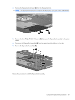
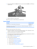
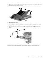
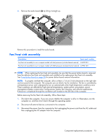
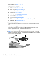
5. Release the system board (4) by sliding it to the right until the connectors on the left side of the system board disengage from the base enclosure. 6. Remove the system board. 7. If it is necessary to replace the USB/power connector board cable, turn the system board upside down with the front toward you. 8. Disconnect the power connector board cable (1) and the USB board cable (2) from the system board. Reverse the above procedure to install the system board and USB/power connector board cable. Component replacement procedures 73
-
 1
1 -
2
-
3
-
4
-
5
-
6
-
7
-
8
-
9
-
10
-
11
-
12
-
13
-
14
-
15
-
16
-
17
-
18
-
19
-
20
-
21
-
22
-
23
-
24
-
25
-
26
-
27
-
28
-
29
-
30
-
31
-
32
-
33
-
34
-
35
-
36
-
37
-
38
-
39
-
40
-
41
-
42
-
43
-
44
-
45
-
46
-
47
-
48
-
49
-
50
-
51
-
52
-
53
-
54
-
55
-
56
-
57
-
58
-
59
-
60
-
61
-
62
-
63
-
64
-
65
-
66
-
67
-
68
-
69
-
70
-
71
-
72
-
73
-
74
-
75
-
 76
76 -
 77
77 -
 78
78 -
 79
79 -
 80
80 -
 81
81 -
 82
82 -
 83
83 -
 84
84 -
 85
85 -
 86
86 -
87
-
88
-
89
-
90
-
91
-
92
-
93
-
94
-
95
-
96
-
97
-
98
-
99
-
100
-
101
-
102
-
103
-
104
-
105
-
106
-
107
-
108
-
109
-
110
-
111
-
112
-
113
-
114
-
115
-
116
-
117
-
118
-
119
-
120
-
121
-
122
-
123
-
124
-
125
-
126
-
127
-
128
-
129
-
130
-
131
-
132
-
133
-
134
-
135
-
136
-
137
-
138
-
139
-
140
-
141
-
142
-
143
-
144
-
145
-
146
-
147
-
148
 |
 |

5
.
Release the system board
(4)
by sliding it to the right until the connectors on the left side of the system
board disengage from the base enclosure.
6
.
Remove the system board.
7
.
If it is necessary to replace the USB/power connector board cable, turn the system board upside
down with the front toward you.
8
.
Disconnect the power connector board cable
(1)
and the USB board cable
(2)
from the system
board.
Reverse the above procedure to install the system board and USB/power connector board cable.
Component replacement procedures
73