HP Presario V6600 Compaq Presario V6500, V6600, and V6700 Notebook PCs - Maint - Page 87
Lift the processor, Turn the processor locking screw
 |
View all HP Presario V6600 manuals
Add to My Manuals
Save this manual to your list of manuals |
Page 87 highlights
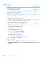
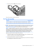
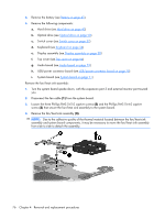
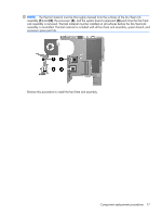
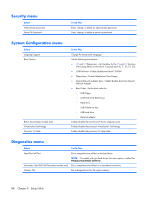
4. Remove the battery (see Battery on page 41). 5. Remove the following components: a. Hard drive (see Hard drive on page 42) b. Optical drive (see Optical drive on page 50) c. Switch cover (see Switch cover on page 52) d. Keyboard (see Keyboard on page 54) e. Display assembly (see Display assembly on page 58) f. Top cover (see Top cover on page 64) g. Audio board (see Audio board on page 74) h. USB/power connector board (see USB/power connector board on page 70) i. System board (see System board on page 71) j. Fan/heat sink assembly (see Fan/heat sink assembly on page 75) Remove the processor: 1. Turn the processor locking screw (1) one-half turn counterclockwise until you hear a click. 2. Lift the processor (2) straight up and remove it. NOTE: The gold triangle (3) on the processor must be aligned with the triangle icon (4) embossed on the processor socket when you install the processor. Reverse this procedure to install the processor. Component replacement procedures 79
-
 1
1 -
2
-
3
-
4
-
5
-
6
-
7
-
8
-
9
-
10
-
11
-
12
-
13
-
14
-
15
-
16
-
17
-
18
-
19
-
20
-
21
-
22
-
23
-
24
-
25
-
26
-
27
-
28
-
29
-
30
-
31
-
32
-
33
-
34
-
35
-
36
-
37
-
38
-
39
-
40
-
41
-
42
-
43
-
44
-
45
-
46
-
47
-
48
-
49
-
50
-
51
-
52
-
53
-
54
-
55
-
56
-
57
-
58
-
59
-
60
-
61
-
62
-
63
-
64
-
65
-
66
-
67
-
68
-
69
-
70
-
71
-
72
-
73
-
74
-
75
-
76
-
77
-
78
-
79
-
80
-
81
-
 82
82 -
 83
83 -
 84
84 -
 85
85 -
 86
86 -
 87
87 -
 88
88 -
 89
89 -
 90
90 -
 91
91 -
 92
92 -
93
-
94
-
95
-
96
-
97
-
98
-
99
-
100
-
101
-
102
-
103
-
104
-
105
-
106
-
107
-
108
-
109
-
110
-
111
-
112
-
113
-
114
-
115
-
116
-
117
-
118
-
119
-
120
-
121
-
122
-
123
-
124
-
125
-
126
-
127
-
128
-
129
-
130
-
131
-
132
-
133
-
134
-
135
-
136
-
137
-
138
-
139
-
140
-
141
-
142
-
143
-
144
-
145
-
146
-
147
-
148
 |
 |
