HP ProDesk 400 G5 Micro Maintenance and Service Guide
HP ProDesk 400 G5 Micro Manual
 |
View all HP ProDesk 400 G5 Micro manuals
Add to My Manuals
Save this manual to your list of manuals |
HP ProDesk 400 G5 Micro manual content summary:
- HP ProDesk 400 G5 Micro | Maintenance and Service Guide - Page 1
Maintenance and Service Guide HP ProDesk 400 G5/G6 MT - HP ProDesk 400 G5 Micro | Maintenance and Service Guide - Page 2
or other countries. SD Logo is a trademark of its proprietor. This guide describes features that are common to most models. Some features may not warranties for HP products and services are set forth in the express warranty statements accompanying such products and services. Nothing herein should be - HP ProDesk 400 G5 Micro | Maintenance and Service Guide - Page 3
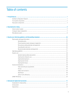
cleaning safety precautions ...28 Cleaning the computer case ...28 Cleaning the keyboard ...28 Cleaning the monitor ...29 Cleaning the mouse ...29 Service considerations ...29 Tools and software requirements ...29 Screws ...29 Cables and connectors ...30 Hard Drives ...30 Lithium coin cell battery - HP ProDesk 400 G5 Micro | Maintenance and Service Guide - Page 4
58 Recovering the Configuration Settings ...63 6 Troubleshooting without diagnostics ...64 Safety and comfort ...64 Before you call for technical support ...64 Helpful hints ...65 Solving general problems ...66 Solving power problems ...69 Solving hard drive problems ...70 Solving media card reader - HP ProDesk 400 G5 Micro | Maintenance and Service Guide - Page 5
Solving software problems ...89 7 POST error messages and diagnostic front panel LEDs and audible codes 90 POST numeric codes and text messages ...90 Interpreting system validation diagnostic front - HP ProDesk 400 G5 Micro | Maintenance and Service Guide - Page 6
Index ...118 vi - HP ProDesk 400 G5 Micro | Maintenance and Service Guide - Page 7
1 Product features Standard configuration features Features can vary depending on the model. For support assistance and to learn more about the hardware and software installed on the computer model, run the HP Support Assistant utility. Standard configuration features 1 - HP ProDesk 400 G5 Micro | Maintenance and Service Guide - Page 8
Front panel components Drive configuration can vary by model. Some models have a bezel blank covering the optical drive bay. Table 1-1 Front panel components and their descriptions (1) Slim optical drive (optional) (4) Audio-out (headphone)/Audio-in (microphone) combo jack* (2) Dual-state - HP ProDesk 400 G5 Micro | Maintenance and Service Guide - Page 9
recommends connecting the keyboard to one of the USB 2.0 ports with the Wake from S4/S5 feature. The Wake from S4/S5 feature is also supported on the PS/2 connectors if enabled in BIOS F10 Setup. When a graphics card is installed in one of the system board slots, the video connectors - HP ProDesk 400 G5 Micro | Maintenance and Service Guide - Page 10
number and a product ID number that are located on the exterior of the computer. Keep these numbers available for use when contacting support for assistance. Computer major components Table 2-1 Computer major components and their descriptions Description Access panel Front bezel SD card blank bezel - HP ProDesk 400 G5 Micro | Maintenance and Service Guide - Page 11
Table 2-1 Computer major components and their descriptions (continued) Description Intel Core i9-9900 3.10-GHz processor (2666-MHz front-side bus [FSB], 16.0-MB SmartCache, eight cores) Intel Core i7-9700 3.00-GHz processor (2666-MHz FSB, 12.0-MB SmartCache, eight cores) Intel Core i5-9600 3.10-GHz - HP ProDesk 400 G5 Micro | Maintenance and Service Guide - Page 12
Table 2-1 Computer major components and their descriptions (continued) Description DVD-BluRay 6x Writer Drive, 9.5-mm, slim DVD±RW SuperMulti Dual Layer Drive, 9.5-mm, slim DVD-ROM Drive, 9.5-mm, slim Optical drive long bezel blank, 9.5-mm, slim Optical drive latch, 9.5-mm, slim Networking: Intel - HP ProDesk 400 G5 Micro | Maintenance and Service Guide - Page 13
Table 2-1 Computer major components and their descriptions (continued) Description 1-TB, 7200-rpm, 9.5-mm 1-TB, 5400-rpm, 7.0-mm, HYBRID 8-GB 500-GB, 7200-rpm, 3.5-in. 500-GB, 7200-rpm, 3.5-in., second hard drive 500-GB, 7200-rpm, 3.5-in., third hard drive 500-GB, 7200-rpm, 3.5-in., SATA, 6.0-GB/sec - HP ProDesk 400 G5 Micro | Maintenance and Service Guide - Page 14
Table 2-1 Computer major components and their descriptions (continued) Description 512-GB solid-state drive with FIPS security 512-GB solid-state drive with FIPS security, second drive 256-GB, M.2 2280, PCIe, NVMe solid-state drive with SS and TLC 256-GB, M.2 2280, PCIe, NVMe solid-state drive with - HP ProDesk 400 G5 Micro | Maintenance and Service Guide - Page 15
Table 2-2 Miscellaneous parts and their descriptions (continued) Description For use in Israel For use in Italy For use in the North America For use in the People's Republic of China For use in South Africa For use in South Korea For use in Switzerland For use in Taiwan For use in the United Kingdom - HP ProDesk 400 G5 Micro | Maintenance and Service Guide - Page 16
Table 2-2 Miscellaneous parts and their descriptions (continued) Description Wireless antenna cable (internal) Expansion cards: DisplayPort option board HDMI option board Parallel port PCIe x1 card VGA option board Graphics cards: AMD Radeon R7 430 2-GB 2DP Card AMD Radeon R7 430 2-GB LP 2DP PCIe×16 - HP ProDesk 400 G5 Micro | Maintenance and Service Guide - Page 17
Table 2-2 Miscellaneous parts and their descriptions (continued) Description For use in the Netherlands For use in Norway For use in the People's Republic of China For use in Poland For use in Portugal For use in Romania For use in Russia For use in Saudi Arabia For use in Spain For use in Sweden - HP ProDesk 400 G5 Micro | Maintenance and Service Guide - Page 18
Table 2-2 Miscellaneous parts and their descriptions (continued) Description For use in Israel For use in Italy For use in Latin America For use in the Netherlands For use in the Northwest Africa For use in Norway For use in Portugal For use in Romania For use in Russia For use in Saudi Arabia For - HP ProDesk 400 G5 Micro | Maintenance and Service Guide - Page 19
Table 2-2 Miscellaneous parts and their descriptions (continued) Description For use in Japan For use in Latin America For use in the Netherlands For use in Northwest Africa For use in Norway For use in the People's Republic of China For use in Portugal For use in Romania For use in Russia For use - HP ProDesk 400 G5 Micro | Maintenance and Service Guide - Page 20
Table 2-2 Miscellaneous parts and their descriptions (continued) Description For use in Italy For use in the Netherlands For use in Northwest Africa For use in Norway For use in Portugal For use in Romania For use in Russia For use in Saudi Arabia For use in SCC For use in Spain For use in Sweden - HP ProDesk 400 G5 Micro | Maintenance and Service Guide - Page 21
Table 2-2 Miscellaneous parts and their descriptions (continued) Description For use in Romania For use in Russia For use in Saudi Arabia For use in SCC For use in Spain For use in Sweden For use in Switzerland For use in Taiwan For use in Turkey For use in the United Kingdom and Singapore For use - HP ProDesk 400 G5 Micro | Maintenance and Service Guide - Page 22
Table 2-2 Miscellaneous parts and their descriptions (continued) Description For use in Romania For use in Russia For use in Saudi Arabia For use in South Korea For use in Spain For use in Sweden For use in Switzerland For use in Taiwan For use in Thailand For use in Turkey For use in the United - HP ProDesk 400 G5 Micro | Maintenance and Service Guide - Page 23
Table 2-2 Miscellaneous parts and their descriptions (continued) Description For use in the Netherlands For use in Northwest Africa For use in Norway For use in the People's Republic of China For use in Portugal For use in Romania For use in Russia For use in Saudi Arabia For use in South Korea For - HP ProDesk 400 G5 Micro | Maintenance and Service Guide - Page 24
Table 2-2 Miscellaneous parts and their descriptions (continued) Description For use in Portugal For use in Romania For use in Russia For use in Saudi Arabia For use in SCC For use in Spain For use in Sweden For use in Switzerland For use in Taiwan For use in Turkey For use in the United Kingdom and - HP ProDesk 400 G5 Micro | Maintenance and Service Guide - Page 25
Table 2-2 Miscellaneous parts and their descriptions (continued) Description For use in Spain For use in Sweden For use in Switzerland For use in Taiwan For use in Turkey For use in the United Kingdom and Singapore For use in the United States HP wireless Windows 8 keyboard/mouse combination with - HP ProDesk 400 G5 Micro | Maintenance and Service Guide - Page 26
Table 2-2 Miscellaneous parts and their descriptions (continued) Description For use in Sweden For use in Switzerland For use in Taiwan For use in Thailand For use in Turkey For use in the United Kingdom and Singapore For use in the United States Katydid black USB keyboard with U.S. layout: For use - HP ProDesk 400 G5 Micro | Maintenance and Service Guide - Page 27
Table 2-2 Miscellaneous parts and their descriptions (continued) Description For use in Russia For use in Saudi Arabia For use in Spain For use in Sweden and Finland For use in Switzerland For use in Turkey For use in the United Kingdom and Singapore Unbranded USB keyboard ME: For use in Belgium For - HP ProDesk 400 G5 Micro | Maintenance and Service Guide - Page 28
Table 2-2 Miscellaneous parts and their descriptions (continued) Description For use in South Korea For use in Spain For use in Sweden For use in Switzerland For use in Taiwan For use in Thailand For use in Turkey For use in United Kingdom and Singapore For use in the United States Unbranded USB - HP ProDesk 400 G5 Micro | Maintenance and Service Guide - Page 29
Table 2-2 Miscellaneous parts and their descriptions (continued) Description For use in Portugal For use in Romania For use in Russia For use in Saudi Arabia For use in South Korea For use in Spain For use in Sweden and Finland For use in Switzerland For use in Taiwan For use in Thailand For use in - HP ProDesk 400 G5 Micro | Maintenance and Service Guide - Page 30
Table 2-2 Miscellaneous parts and their descriptions (continued) Description HP USB laser mouse HP USB mouse in grey finish HP USB mouse in grey finish v.2 HP USB optical mouse HP USB premium mouse Moonraker Healthcare USB wired mouse USB PS/2 washable mouse USB 3.0 SD Card reader Wired local area - HP ProDesk 400 G5 Micro | Maintenance and Service Guide - Page 31
information for the computer. Adherence to the procedures and precautions described in this chapter is essential for proper service. CAUTION: When the computer is plugged into an AC power source, voltage is always applied to the system board. The power cord must be disconnected - HP ProDesk 400 G5 Micro | Maintenance and Service Guide - Page 32
Preventing electrostatic damage to equipment Many electronic components are sensitive to ESD. Circuitry design and structure determine the degree of sensitivity. The following packaging and grounding precautions are necessary to prevent damage to electric components and accessories. ● To avoid hand - HP ProDesk 400 G5 Micro | Maintenance and Service Guide - Page 33
tabletop workstations with ground cords of 1 MΩ ±10% resistance ● Static-dissipative table or floor mats with hard ties to ground ● Field service kits ● Static awareness labels ● Wrist straps and footwear straps providing 1 MΩ ±10% resistance ● Material handling packages ● Conductive plastic bags - HP ProDesk 400 G5 Micro | Maintenance and Service Guide - Page 34
● Never cover the ventilation slots on the monitor with any type of material. ● Install or enable power management functions of the operating system or other software, including sleep states. Routine care General cleaning safety precautions 1. Never use solvents or flammable solutions to clean the - HP ProDesk 400 G5 Micro | Maintenance and Service Guide - Page 35
ball with a clean, dry cloth before reassembly. ● To clean the mouse body, follow the procedures in Cleaning the computer case on page 28. Service considerations Listed below are some of the considerations that you should keep in mind during the disassembly and assembly of the computer. Tools and - HP ProDesk 400 G5 Micro | Maintenance and Service Guide - Page 36
or snagged by parts being removed or replaced. CAUTION: When servicing this computer, ensure that cables are placed in their proper location replacement chapter for the chassis you are working on in this guide for instructions on the replacement procedures. WARNING! This computer contains a lithium - HP ProDesk 400 G5 Micro | Maintenance and Service Guide - Page 37
operate properly. NOTE: Not all features listed in this guide are available on all computers. Preparation for disassembly WARNING! Voltage "Standby," or "Suspend" modes. The power cord should always be disconnected before servicing a unit. NOTE: During disassembly, label each cable as you remove it, - HP ProDesk 400 G5 Micro | Maintenance and Service Guide - Page 38
Access panel 1. Prepare the computer for disassembly (see Preparation for disassembly on page 31). 2. Position the computer with the rear toward you. 3. Loosen the access panel security screw (1). 4. Use the access panel release handle (2) to pull the access panel back. 5. Remove the access panel - HP ProDesk 400 G5 Micro | Maintenance and Service Guide - Page 39
Optical drive 1. Prepare the computer for disassembly (see Preparation for disassembly on page 31). 2. Remove the access panel (see Access panel on page 32). 3. Disconnect the power cable (1) from the optical drive. 4. Disconnect the data cable (2) from the optical drive. 5. Press the optical drive - HP ProDesk 400 G5 Micro | Maintenance and Service Guide - Page 40
Reverse this procedure to install the optical drive. Dust filter 1. Prepare the computer for disassembly (see Preparation for disassembly on page 31). 2. Remove the access panel (see Access panel on page 32). 3. Position the computer in the tower mode with the front facing you. 4. Remove the dust - HP ProDesk 400 G5 Micro | Maintenance and Service Guide - Page 41
Front bezel 1. Prepare the computer for disassembly (see Preparation for disassembly on page 31). 2. Remove the access panel (see Access panel on page 32). 3. Detach the three clips (1) on the top edge of the front bezel from the tabs on the computer chassis. 4. Swing the top edge of the front cover - HP ProDesk 400 G5 Micro | Maintenance and Service Guide - Page 42
Drive cage Follow these steps to remove the drive cage: 1. Prepare the computer for disassembly (see Preparation for disassembly on page 31). 2. Remove the access panel (see Access panel on page 32). 3. Disconnect the power cable (1) from the 3.5-inch hard drive. 4. Disconnect the data cable (2) - HP ProDesk 400 G5 Micro | Maintenance and Service Guide - Page 43
6. Disconnect the data cable (2) from the 2.5-inch hard drive. 7. Lift the rear edge of the drive cage (1) to disengage it from the computer chassis. 8. Slide the drive cage (2) away from the computer chassis. 9. Remove the drive cage (3). Reverse this procedure to install the drive cage. Drive - HP ProDesk 400 G5 Micro | Maintenance and Service Guide - Page 44
Hard drives Follow these steps to remove a 3.5-inch hard drive: 1. Prepare the computer for disassembly (see Preparation for disassembly on page 31). 2. Remove the access panel (see Access panel on page 32). 3. Remove the drive cage (see Drive cage on page 36). 4. Remove the two Torx-15 M3.0×9.0 - HP ProDesk 400 G5 Micro | Maintenance and Service Guide - Page 45
5. Remove the 2.5-inch hard drive (2) from the drive cage. Reverse this procedure to install the hard drives. Hard drives 39 - HP ProDesk 400 G5 Micro | Maintenance and Service Guide - Page 46
Fan Follow these steps to remove the speaker: 1. Prepare the computer for disassembly (see Preparation for disassembly on page 31). 2. Remove the access panel (see Access panel on page 32). 3. Position the computer with the front panel toward you. 4. Disconnect the fan cable (1) from the system - HP ProDesk 400 G5 Micro | Maintenance and Service Guide - Page 47
. If you replace the module and then receive a warning message, remove the module to restore device functionality, and then contact technical support. Before removing the WLAN module, follow these steps: 1. Prepare the computer for disassembly (see Preparation for disassembly on page 31). 2. Remove - HP ProDesk 400 G5 Micro | Maintenance and Service Guide - Page 48
Solid-state drive Before removing the solid-state drive, follow these steps: 1. Prepare the computer for disassembly (see Preparation for disassembly on page 31). 2. Remove the access panel (see Access panel on page 32). 3. Remove the front bezel (see Front bezel on page 35). 4. Remove the drive - HP ProDesk 400 G5 Micro | Maintenance and Service Guide - Page 49
Memory module The computer has four memory module sockets. CAUTION: You must disconnect the power cord and wait approximately 30 seconds for the power to drain before adding or removing memory modules. Regardless of the power-on state, voltage is always supplied to the memory modules as long as the - HP ProDesk 400 G5 Micro | Maintenance and Service Guide - Page 50
Speaker Follow these steps to remove the speaker: 1. Prepare the computer for disassembly (see Preparation for disassembly on page 31). 2. Remove the access panel (see Access panel on page 32). 3. Remove the front bezel (see Front bezel on page 35). 4. Remove the drive cage (see Drive cage on page - HP ProDesk 400 G5 Micro | Maintenance and Service Guide - Page 51
Power supply Follow these steps to remove the power supply: 1. Prepare the computer for disassembly (see Preparation for disassembly on page 31). 2. Remove the access panel (see Access panel on page 32). 3. Remove the front bezel (see Front bezel on page 35). 4. Remove the drive cage (see Drive cage - HP ProDesk 400 G5 Micro | Maintenance and Service Guide - Page 52
Fan-sink NOTE: The fan-sink spare part kit includes replacement thermal material. Follow these steps to remove the fan-sink: 1. Prepare the computer for disassembly (see Preparation for disassembly on page 31). 2. Remove the access panel (see Access panel on page 32). 3. Remove the front bezel (see - HP ProDesk 400 G5 Micro | Maintenance and Service Guide - Page 53
Processor NOTE: The processor spare part kit includes replacement thermal material. Follow these steps to remove the fan-sink: 1. Prepare the computer for disassembly (see Preparation for disassembly on page 31), and then remove the following components: 2. Remove the access panel (see Access panel - HP ProDesk 400 G5 Micro | Maintenance and Service Guide - Page 54
4. Lift the processor (4) straight up, and remove it. CAUTION: When installing the processor, the gold triangle (1) on the processor must be aligned with the triangle icon (2) embossed on the system board. Failure to follow this caution can result in damage to the pins on the processor and system - HP ProDesk 400 G5 Micro | Maintenance and Service Guide - Page 55
System board NOTE: The system board spare part kit includes replacement thermal material. Follow these steps to remove the system board: 1. Prepare the computer for disassembly (see Preparation for disassembly on page 31). 2. Remove the access panel (see Access panel on page 32), and then remove the - HP ProDesk 400 G5 Micro | Maintenance and Service Guide - Page 56
4. Remove the eight Torx-15 M3.0×9.0 screws that secure the system board to the computer chassis. 5. Slide the system board (1) forward through the opening in the front of the computer chassis. 6. Swing the rear edge of the system board (2) up and forward until the components on the rear edge are - HP ProDesk 400 G5 Micro | Maintenance and Service Guide - Page 57
Connector board Follow these steps to remove the connector board: 1. Prepare the computer for disassembly (see Preparation for disassembly on page 31). 2. Remove the access panel (see Access panel on page 32), and then remove the following components: a. Front bezel (see Front bezel on page 35) b. - HP ProDesk 400 G5 Micro | Maintenance and Service Guide - Page 58
until they are unsecured. ● Enable or disable different types of boot sources. ● Configure features such as Secure Boot, power management, virtualization support, and language and keyboard type used in Setup and POST. ● Replicate the system setup by saving system configuration information on a USB - HP ProDesk 400 G5 Micro | Maintenance and Service Guide - Page 59
Using Computer Setup (F10) Utilities Computer Setup can be accessed only by turning the computer on or restarting the system. To access the Computer Setup Utilities menu, complete the following steps: 1. Turn on or restart the computer. 2. Repeatedly press F10 when the monitor light turns green to - HP ProDesk 400 G5 Micro | Maintenance and Service Guide - Page 60
Computer Setup-Main NOTE: Support for specific Computer Setup options can vary depending on the hardware configuration. Table 5-1 Computer Setup-Main Option Description System Information System Diagnostics Update System BIOS - HP ProDesk 400 G5 Micro | Maintenance and Service Guide - Page 61
Table 5-1 Computer Setup-Main (continued) Option Description ● Lock BIOS Version If this option is checked, the system is locked to the current BIOS version and updates are not allowed. ● BIOS Update Preferences Allows the administrator to select the source of network updates (www.hp.com or - HP ProDesk 400 G5 Micro | Maintenance and Service Guide - Page 62
Computer Setup-Security NOTE: Support for specific Computer Setup options can vary depending on the hardware configuration. Table 5-2 Computer Setup-Security Option Description Set up BIOS Administrator Password Lets you - HP ProDesk 400 G5 Micro | Maintenance and Service Guide - Page 63
● Data Recovery Policy Select Automatic or Manual to set data recovery policy. Manual lets you select whether or not to execute not formatted to include an MBR. Instead they use GUID Partition Table (GPT) format, which better supports large hard drives. Enabling this feature will save the - HP ProDesk 400 G5 Micro | Maintenance and Service Guide - Page 64
Management Command Allows authorized personnel to reset security settings during a service event. Default is enabled. Restore Security Settings This action Security menu to factory defaults. Computer Setup-Advanced NOTE: Support for specific Computer Setup options can vary depending on the - HP ProDesk 400 G5 Micro | Maintenance and Service Guide - Page 65
Disabling this setting alters the Secure Boot key list to further restrict the allowed software components. Set this option to disable to support Device Guard. System Options Configure Storage Controller for RAID (enable/disable) Lets you enable onboard RAID. Default is disabled. POST Prompt for - HP ProDesk 400 G5 Micro | Maintenance and Service Guide - Page 66
Table 5-3 Computer Setup-Advanced (for advanced users) (continued) Option Heading Controls the virtualization features of the processor. Changing this setting requires turning the computer off and then back on. Default is disabled. Virtualization Technology for Directed I/O (VTd) (Intel only) - HP ProDesk 400 G5 Micro | Maintenance and Service Guide - Page 67
Table 5-3 Computer Setup-Advanced (for advanced users) (continued) Option Heading Clear to disable the display panel touch feature. Default is enabled. Port Options Allows you to hide the following ports from the operating system: ● Serial port A ● Serial port B ● SATA0 ● SATA1 ● SATA2 ● SATA3 - HP ProDesk 400 G5 Micro | Maintenance and Service Guide - Page 68
computing devices. USB Key Provisioning Support (enable/disable). Default is disabled. USB Redirection Support (enable/disable). Default is ) CIRA is Customer Initiated Remote Assistance, an Intel service to help users employing Active Management Technology (AMT). 62 Chapter 5 Computer Setup ( - HP ProDesk 400 G5 Micro | Maintenance and Service Guide - Page 69
Recovering the Configuration Settings This method of recovery requires that you first perform the Save to Removable Media command with the Computer Setup (F10) Utility before Restore is needed. (See Computer Setup-Main on page 54 in the Computer Setup-File table.) The Save to Removable Media option - HP ProDesk 400 G5 Micro | Maintenance and Service Guide - Page 70
Troubleshooting without diagnostics This chapter provides information on how to identify and correct minor problems, such as USB devices, hard drive, graphics, audio, memory, and software problems. If you encounter problems guide. Before you call for technical support If you are having problems with - HP ProDesk 400 G5 Micro | Maintenance and Service Guide - Page 71
monitor serial number before calling. ● Spend time troubleshooting the problem with the service technician. ● Remove any hardware that was recently expansion board or other option. See Solving hardware installation problems on page 82 for instructions. ● Be sure that all the needed device drivers - HP ProDesk 400 G5 Micro | Maintenance and Service Guide - Page 72
check to be sure that it is supported on the system. ● If the problems You may be able to easily resolve the general problems described in this section. If a problem displayed. - or - Follow the Windows instructions for rebooting the computer into the Computer Setup Troubleshooting without diagnostics - HP ProDesk 400 G5 Micro | Maintenance and Service Guide - Page 73
date and time). If the problem persists, replace the RTC battery. See the Removal and Replacement section for instructions on installing a new battery, In case of forgotten password, power loss, or computer malfunction, you must manually disable the Smart Cover lock . A key to unlock the Smart Cover - HP ProDesk 400 G5 Micro | Maintenance and Service Guide - Page 74
voltage selector (located on the rear of the power supply) is set to the appropriate voltage. Proper voltage setting depends on your region. 68 Chapter 6 Troubleshooting without diagnostics - HP ProDesk 400 G5 Micro | Maintenance and Service Guide - Page 75
5V_aux light on the system board is off, then replace the power supply. 6. Replace the system board. Solving power problems Common causes and solutions for power problems are listed in the following table. Power supply shuts down intermittently. Cause If equipped with a voltage selector, voltage - HP ProDesk 400 G5 Micro | Maintenance and Service Guide - Page 76
3. Check if a device is causing the problem by removing all attached devices (such as the system board. Solving hard drive problems Hard drive error occurs. Cause problem. Cause Solution Either the directory structure is bad or there is a problem Solving hardware installation problems on page 82 - HP ProDesk 400 G5 Micro | Maintenance and Service Guide - Page 77
responds slowly immediately after power-up. Solution Computer Setup. If it is listed, the probable cause is a driver problem. If it is not listed, the probable cause is a hardware problem. If this is a newly installed drive, run the Computer Setup utility and try adding a POST delay under Advanced - HP ProDesk 400 G5 Micro | Maintenance and Service Guide - Page 78
the computer, press the power button again. Solving media card reader problems Media card will not work in a digital camera after formatting it in is not inserted properly, is inserted in the wrong slot, or is not supported. Ensure that the card is inserted properly with the gold contact on the - HP ProDesk 400 G5 Micro | Maintenance and Service Guide - Page 79
(Power On Self-Test), press F9 to modify the boot menu. 3. Change the boot sequence in F10 Computer Setup. Solving display problems If you encounter display problems, see the documentation that came with the monitor and to the common causes and solutions listed in the following table. Blank screen - HP ProDesk 400 G5 Micro | Maintenance and Service Guide - Page 80
). Power on the system. 2. Replace the graphics card (if applicable). 3. Replace the system board. For systems with integrated graphics, replace the system board. 74 Chapter 6 Troubleshooting without diagnostics - HP ProDesk 400 G5 Micro | Maintenance and Service Guide - Page 81
may be too close to the monitor. Monitor needs to be degaussed. Degauss the monitor. Refer to the documentation that came with the monitor for instructions. Solving display problems 75 - HP ProDesk 400 G5 Micro | Maintenance and Service Guide - Page 82
higher than what the monitor supports. Solution Restart the computer and enter Safe Mode. Change the settings to a supported setting then restart the computer Adjustment option in the monitor's on-screen display menu. 2. Manually synchronize the Clock and Clock Phase on-screen display functions. - HP ProDesk 400 G5 Micro | Maintenance and Service Guide - Page 83
do not appear correct. Cause The font you are using does not support that particular symbol. Solution Use the Character Map to locate and select the list of applications. Solving audio problems If the computer has audio features and you encounter audio problems, see the common causes and solutions - HP ProDesk 400 G5 Micro | Maintenance and Service Guide - Page 84
jack supports only Cellular Telephone Industries Association (CTIA) style headsets. Open Mobile Terminal Platform (OMTP) style headsets are not supported. These styles of headsets differ by the way that the microphone signals are oriented on the 78 Chapter 6 Troubleshooting without diagnostics - HP ProDesk 400 G5 Micro | Maintenance and Service Guide - Page 85
to use a different audio device than speakers. Some graphics cards support audio over the DisplayPort connection (if applicable), so multiple audio devices to use the correct audio device. Solving printer problems If you encounter printer problems, see the documentation that came with the printer - HP ProDesk 400 G5 Micro | Maintenance and Service Guide - Page 86
the paper tray and refill it if it is empty. Solving keyboard and mouse problems If you encounter keyboard or mouse problems, see the documentation that came with the equipment and to the common causes and down and you will lose any unsaved data. 80 Chapter 6 Troubleshooting without diagnostics - HP ProDesk 400 G5 Micro | Maintenance and Service Guide - Page 87
cover from the bottom of the mouse and clean the internal components with a mouse cleaning kit available from most computer stores. Solving keyboard and mouse problems 81 - HP ProDesk 400 G5 Micro | Maintenance and Service Guide - Page 88
the new hardware. In Windows, use the Add Hardware Wizard and follow the instructions that appear on the screen. To open the Add Hardware Wizard, open a codes for specific problems. 3. If you still cannot resolve the issue, contact Customer Support. 82 Chapter 6 Troubleshooting without diagnostics - HP ProDesk 400 G5 Micro | Maintenance and Service Guide - Page 89
are listed in the following table. These guidelines do not discuss the process of debugging the network cabling. Table 6-2 Solving network problems Network driver does not detect network controller. Cause Network controller is disabled. Incorrect network driver. Solution 1. Run Computer Setup and - HP ProDesk 400 G5 Micro | Maintenance and Service Guide - Page 90
. The cable is attached to the incorrect connector. There is a problem with the cable or a device at the other end of the the other end are operating correctly. Contact an authorized service provider. Diagnostics passes, but the computer does not communicate 6 Troubleshooting without diagnostics - HP ProDesk 400 G5 Micro | Maintenance and Service Guide - Page 91
end of the cable is securely attached to the correct device. Contact an authorized service provider. New network card will not boot. Cause New network card may be defective unprogrammed EEPROM. Cause Unprogrammed EEPROM. Solution Contact an authorized service provider. Solving network problems 85 - HP ProDesk 400 G5 Micro | Maintenance and Service Guide - Page 92
If you encounter memory problems, some common causes and reseat, install, or remove a memory module. For those systems that support ECC memory, HP does not support mixing ECC and non-ECC memory. Otherwise, the computer will not boot to the computer. 86 Chapter 6 Troubleshooting without diagnostics - HP ProDesk 400 G5 Micro | Maintenance and Service Guide - Page 93
time to isolate the faulty module. 3. Replace third-party memory with HP memory. 4. Replace the system board. Solving USB flash drive problems If you encounter USB flash drive problems, common causes and solutions are listed in the following table. USB flash drive is not seen as a drive letter in - HP ProDesk 400 G5 Micro | Maintenance and Service Guide - Page 94
to Enabled in Security > USB Security. Solving Internet access problems If you encounter Internet access problems, consult your Internet Service Provider (ISP) or refer to the common causes and the list of applications. Click Internet Options. 88 Chapter 6 Troubleshooting without diagnostics - HP ProDesk 400 G5 Micro | Maintenance and Service Guide - Page 95
been installed. ● If you have installed an operating system other than the factory-installed operating system, it might not be supported on the system. If you encounter software problems, see the applicable solutions listed in the following table. Computer will not continue and the HP logo does not - HP ProDesk 400 G5 Micro | Maintenance and Service Guide - Page 96
-Test (POST) or computer restart, the probable source of the problem, and steps you can take to resolve the error condition. POST messages. If a POST error occurs, the screen will display the error message. To manually switch to the POST Messages Enabled mode during POST, press any key (except F10, - HP ProDesk 400 G5 Micro | Maintenance and Service Guide - Page 97
action RTC (real-time clock) battery may need to be replaced. the problem persists, replace the RTC battery. See the Removal and Replacement section for instructions on installing a new battery. Processor is not supported by the BIOS. 1. Upgrade BIOS to proper version. 2. Change the processor - HP ProDesk 400 G5 Micro | Maintenance and Service Guide - Page 98
ECC 1. If additional memory was recently added, memory error correction. remove it to see if the problem remains. 2. Check product documentation for memory support information. 2E6-Memory Not Configured Correctly for Proper DIMM1 is not installed. MEBx Execution Make sure there is a memory - HP ProDesk 400 G5 Micro | Maintenance and Service Guide - Page 99
System test under using F2 Diagnostics when booting the computer. 2. Apply hard drive firmware patch if applicable. (Available at http://www.hp.com/support.) 3. Back up contents and replace hard drive. 1. Determine if hard drive is giving correct error message. Run the Drive Protection System test - HP ProDesk 400 G5 Micro | Maintenance and Service Guide - Page 100
41B-Device in PCI Express Slot Failed To Initialize There is an incompatibility or problem with a PCIe device and the system or PCIe link could not be installed in the system that is not supported and has been disabled. Replace with a supported module. 800-Keyboard Error Keyboard failure - HP ProDesk 400 G5 Micro | Maintenance and Service Guide - Page 101
Control panel message 90D-System Temperature 90E-Power Supply Fan Not detected 910-Filter Warning Description Recommended action 3. Replace fan. Thermal shutdown occurred. The system BIOS has detected your machine was previously shut down to avoid overheating. Overheating may occur if the - HP ProDesk 400 G5 Micro | Maintenance and Service Guide - Page 102
initialization. 3.4 The system board displays a power failure (crowbar).* 3.5 The processor is not detected.* 3.6 The processor does not support an enabled feature. Thermal 4.2 A processor over temperature condition has been detected.* 4.3 An ambient temperature over temperature condition - HP ProDesk 400 G5 Micro | Maintenance and Service Guide - Page 103
or forget the password when in stringent security mode, the system can only be reset by System Management Command. This is a way for HP Service and Support to provide a secure method to access the BIOS and command a password reset for a specifically identified unit under the direction of the owner - HP ProDesk 400 G5 Micro | Maintenance and Service Guide - Page 104
or forget the password when in stringent security mode, the system can only be reset by System Management Command. This is a way for HP Service and Support to provide a secure method to access the BIOS and command a password reset for a specifically identified unit under the direction of the owner - HP ProDesk 400 G5 Micro | Maintenance and Service Guide - Page 105
these procedures, ensure that you are discharged of static electricity by briefly touching a grounded metal object. See the Safety & Regulatory Information guide for more information. 3. Remove the access panel. 4. Locate the header and jumper labeled CMOS/PSWD. NOTE: The password jumper is blue - HP ProDesk 400 G5 Micro | Maintenance and Service Guide - Page 106
Changing a Setup or Power-on password To change the power-on or setup password, complete the following steps: 1. Turn on or restart the computer. To change the Setup password, go to step 2. To change the Power-on password, go to step 3. 2. To change the Setup password, as soon as the computer turns - HP ProDesk 400 G5 Micro | Maintenance and Service Guide - Page 107
-digit Failure ID is generated. This ID can then be provided to support to help determine how to correct the problem. To start HP PC Hardware Diagnostics (UEFI), follow these steps: 1. want to run, and then follow the onscreen instructions. NOTE: If you need to stop a diagnostic test, press esc. 101 - HP ProDesk 400 G5 Micro | Maintenance and Service Guide - Page 108
Diagnostics (UEFI) to a USB device NOTE: The HP PC Hardware Diagnostics (UEFI) download instructions are provided in English only, and you must use a Windows computer to download and create the HP UEFI support environment because only .exe files are offered. There are two options to download HP PC - HP ProDesk 400 G5 Micro | Maintenance and Service Guide - Page 109
flash drive. To download the tool: ▲ Go to the Microsoft Store and search for HP Cloud Recovery. For details, go to http://www.hp.com/support, search for HP Cloud Recovery, and then select "HP PCs - Using the Cloud Recovery Tool (Windows 10, 7)." Backing up information and creating recovery media - HP ProDesk 400 G5 Micro | Maintenance and Service Guide - Page 110
only) on page 103. NOTE: If you cannot create recovery media yourself, contact support to obtain recovery discs. Go to http://www.hp.com/support, select your country or region, and then follow the on-screen instructions. To recover your system: ▲ Insert the HP Recovery media, and then restart the - HP ProDesk 400 G5 Micro | Maintenance and Service Guide - Page 111
device drivers ● Software applications, in the case of a custom image To access the latest documentation for HP Sure Recover, go to http://www.hp.com/support. Select Find your product, and then follow the on-screen instructions. Restoring and recovery 105 - HP ProDesk 400 G5 Micro | Maintenance and Service Guide - Page 112
to remove an internal component to gain access to the battery. 7. Depending on the type of battery holder on the system board, complete the following instructions to replace the battery. Type 1 a. Lift the battery out of its holder. 106 Appendix A Battery replacement - HP ProDesk 400 G5 Micro | Maintenance and Service Guide - Page 113
b. Slide the replacement battery into position, positive side up. The battery holder automatically secures the battery in the proper position. Type 2 a. To release the battery from its holder, squeeze the metal clamp that extends above one edge of the battery. When the battery pops up, lift it out - HP ProDesk 400 G5 Micro | Maintenance and Service Guide - Page 114
b. Insert the new battery and position the clip back into place. NOTE: After the battery has been replaced, use the following steps to complete this procedure. 8. Replace the access panel. 9. Plug in the computer and turn on power to the computer. 10. Reset the date and time, your passwords, and any - HP ProDesk 400 G5 Micro | Maintenance and Service Guide - Page 115
The purpose of this appendix is to provide general information regarding nonvolatile memory in HP Business PCs. This appendix also provides general instructions for restoring nonvolatile memory that can contain personal data after the system has been powered off and the hard drive has been removed - HP ProDesk 400 G5 Micro | Maintenance and Service Guide - Page 116
Hard Drive Utilities. d. Under Utilities, select Secure Erase, select the hard drive storing the data you want to clear, and then follow the on-screen instructions to continue. 110 Appendix B Statement of memory volatility - HP ProDesk 400 G5 Micro | Maintenance and Service Guide - Page 117
Controller. critical System by the HP Sure Start BIOS code, EC Embedded Controller. firmware, and critical PC configuration data for select platforms that support HP Sure Start. For more information, see Using HP Sure Start on page 114. Yes Stores system RTC battery backed-up CMOS This - HP ProDesk 400 G5 Micro | Maintenance and Service Guide - Page 118
? What is the purpose of this memory? How is data input into this memory? How is this memory writeprotected? follow the on-screen instructions. Yes Stores Management Engine Code is The Intel chipset is Management programmed at the factory. configured to enforce Engine Code, Code is updated - HP ProDesk 400 G5 Micro | Maintenance and Service Guide - Page 119
Restore defaults. c. Follow the on-screen instructions. d. Select Main, select Save Changes and Exit, and then follow the on-screen instructions. 2. What is a UEFI BIOS, ). It is a replacement for the older BIOS architecture, but supports much of the legacy BIOS functionality. Like the legacy BIOS, - HP ProDesk 400 G5 Micro | Maintenance and Service Guide - Page 120
. The default configuration can be customized by advanced users. To access the latest documentation on HP Sure Start, go to http://www.hp.com/support, and select your country. Select Drivers & Downloads, and then follow the on-screen instructions. 114 Appendix B Statement of memory volatility - HP ProDesk 400 G5 Micro | Maintenance and Service Guide - Page 121
C Power cord set requirements The power supplies on some computers have external power switches. The voltage select switch feature on the computer permits it to operate from any line voltage between 100-120 or 220-240 volts AC. Power supplies on those computers that do not have external power - HP ProDesk 400 G5 Micro | Maintenance and Service Guide - Page 122
Country-specific requirements Additional requirements specific to a country are shown in parentheses and explained below. Country Accrediting Agency Country Accrediting Agency Australia (1) Austria (1) Belgium (1) Canada (2) EANSW OVE CEBC CSA Italy (1) Japan (3) Norway (1) Sweden (1) IMQ - HP ProDesk 400 G5 Micro | Maintenance and Service Guide - Page 123
(in the desktop position) Height Width Depth 95 mm 270 mm 300 mm 3.7 in 10.6 in 11.8 in Approximate Weight 4.43 kg 9.8 lb Weight Supported (maximum distributed load in desktop position) 35 kg 77 lb Temperature Range Operating Nonoperating 10°C to 35°C -30°C to 60°C 50°F to 95°F -22 - HP ProDesk 400 G5 Micro | Maintenance and Service Guide - Page 124
panel 3 computer serial number 4 computer cleaning 28 Computer Setup access problem 66 connector board removal and replacement 51 connectors DisplayPort monitor 3 power 3 VGA monitor 3 country power cord set requirements 116 Customer Support 64 D deleting a Power-On password 100 deleting a Setup - HP ProDesk 400 G5 Micro | Maintenance and Service Guide - Page 125
S safety and comfort 64 safety precautions cleaning 28 screws, correct size 29 serial port 3 service considerations 29 Setup password 100 setup password 97 slim optical drive location 2 software problems 89 servicing computer 29 solid-state drive removal 42 spare part numbers 42 speaker removal and - HP ProDesk 400 G5 Micro | Maintenance and Service Guide - Page 126
VGA monitor connector 3 W Windows backup 103 recovery media 103 system restore point 103 Windows tools, using 103 WLAN module removal 41 spare part number 41 120 Index
-
 1
1 -
 2
2 -
 3
3 -
 4
4 -
 5
5 -
 6
6 -
 7
7 -
8
-
9
-
10
-
11
-
12
-
13
-
14
-
15
-
16
-
17
-
18
-
19
-
20
-
21
-
22
-
23
-
24
-
25
-
26
-
27
-
28
-
29
-
30
-
31
-
32
-
33
-
34
-
35
-
36
-
37
-
38
-
39
-
40
-
41
-
42
-
43
-
44
-
45
-
46
-
47
-
48
-
49
-
50
-
51
-
52
-
53
-
54
-
55
-
56
-
57
-
58
-
59
-
60
-
61
-
62
-
63
-
64
-
65
-
66
-
67
-
68
-
69
-
70
-
71
-
72
-
73
-
74
-
75
-
76
-
77
-
78
-
79
-
80
-
81
-
82
-
83
-
84
-
85
-
86
-
87
-
88
-
89
-
90
-
91
-
92
-
93
-
94
-
95
-
96
-
97
-
98
-
99
-
100
-
101
-
102
-
103
-
104
-
105
-
106
-
107
-
108
-
109
-
110
-
111
-
112
-
113
-
114
-
115
-
116
-
117
-
118
-
119
-
120
-
121
-
122
-
123
-
124
-
125
-
126
 |
 |

Maintenance and Service Guide
HP ProDesk 400 G5/G6 MT