HP ProDesk 600 G1 EliteDesk 800 G1 Desktop Mini ProDesk 600 G1 Desktop Mini Ma - Page 54
Fan, Remove the four Torx screws that secure the fan to the computer
 |
View all HP ProDesk 600 G1 manuals
Add to My Manuals
Save this manual to your list of manuals |
Page 54 highlights
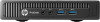
Fan Description Fan Spare part number 768424-001 The fan is located under the heat sink. It is secured with four Torx screws. To remove the fan assembly: 1. Prepare the computer for disassembly (see Preparing to disassemble the computer on page 25). 2. Remove the access panel (see Access panel on page 26). 3. Remove the heat sink (see Heat sink on page 43). 4. Disconnect the fan cable from the system board connector labeled CHFAN (1). 5. Remove the four Torx screws that secure the fan to the computer (2). 6. Remove the fan from the computer. To install the fan assembly, reverse the removal procedures. NOTE: To avoid damaging the rubber screw grommets installed around the captive screws, when installing the fan, push down on the fan assembly before you tighten the screws. Make sure the grommets are positioned correctly before tightening the screws. 46 Chapter 5 Removal and Replacement Procedures
-
 1
1 -
2
-
3
-
4
-
5
-
6
-
7
-
8
-
9
-
10
-
11
-
12
-
13
-
14
-
15
-
16
-
17
-
18
-
19
-
20
-
21
-
22
-
23
-
24
-
25
-
26
-
27
-
28
-
29
-
30
-
31
-
32
-
33
-
34
-
35
-
36
-
37
-
38
-
39
-
40
-
41
-
42
-
43
-
44
-
45
-
46
-
47
-
48
-
 49
49 -
 50
50 -
 51
51 -
 52
52 -
 53
53 -
 54
54 -
 55
55 -
 56
56 -
 57
57 -
 58
58 -
 59
59 -
60
-
61
-
62
-
63
-
64
-
65
-
66
-
67
-
68
-
69
-
70
-
71
-
72
-
73
-
74
-
75
-
76
-
77
-
78
-
79
-
80
-
81
-
82
-
83
-
84
-
85
-
86
-
87
-
88
-
89
-
90
-
91
-
92
-
93
-
94
-
95
-
96
-
97
-
98
-
99
-
100
-
101
-
102
-
103
-
104
-
105
-
106
-
107
-
108
-
109
-
110
-
111
-
112
-
113
-
114
-
115
-
116
-
117
-
118
-
119
-
120
-
121
-
122
-
123
-
124
-
125
-
126
-
127
-
128
-
129
-
130
-
131
-
132
-
133
-
134
-
135
-
136
-
137
-
138
-
139
-
140
-
141
-
142
-
143
-
144
-
145
-
146
-
147
-
148
-
149
-
150
-
151
-
152
-
153
-
154
-
155
-
156
-
157
-
158
-
159
-
160
-
161
-
162
-
163
-
164
-
165
-
166
 |
 |
