HP ProLiant BL420c HP ProLiant BL420c Gen8 Server Blade Maintenance and Servic - Page 56
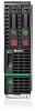
Server blade release lever assembly
 |
View all HP ProLiant BL420c manuals
Add to My Manuals
Save this manual to your list of manuals |
Page 56 highlights
18. Install the hard drives ("Drive" on page 26). 19. Install the hard drive blanks ("Drive blank" on page 26). 20. Install the access panel ("Access panel" on page 25). 21. Install the server blade. After you replace the system board, you must re-enter the server blade serial number and the product ID. 1. During the server blade startup sequence, press the F9 key to access RBSU. 2. Select the Advanced Options menu. 3. Select Service Options. 4. Select Serial Number. The following warning appears: Warning: The serial number should ONLY be modified by qualified service personnel. This value should always match the serial number located on the chassis. 5. Press the Enter key to clear the warning. 6. Enter the serial number and press the Enter key. 7. Select Product ID. The following warning appears: Warning: The Product ID should ONLY be modified by qualified service personnel. This value should always match the Product ID located on the chassis. 8. Enter the product ID and press the Enter key. 9. Press the Esc key to close the menu. 10. Press the Esc key to exit RBSU. 11. Press the F10 key to confirm exiting RBSU. The server blade automatically reboots. Server blade release lever assembly To remove the component: 1. Power down the server blade (on page 23). 2. Remove the server blade (on page 24). 3. Remove the access panel ("Access panel" on page 25). 4. Remove all hard drives ("Drive" on page 26). 5. Remove all hard drive blanks ("Drive blank" on page 26). 6. Disconnect the capacitor pack cabling, if connected ("FBWC capacitor pack cabling" on page 67). 7. Remove the SAS controller ("SAS controller" on page 28). 8. Remove all DIMM baffles ("DIMM baffles" on page 29). 9. Remove all DIMMs ("DIMMs" on page 31). 10. Remove the heatsink blank, if installed ("Heatsink blank" on page 32). 11. Remove the front panel/hard drive cage assembly ("Front panel/drive cage assembly" on page 43). Removal and replacement procedures 56
-
 1
1 -
2
-
3
-
4
-
5
-
6
-
7
-
8
-
9
-
10
-
11
-
12
-
13
-
14
-
15
-
16
-
17
-
18
-
19
-
20
-
21
-
22
-
23
-
24
-
25
-
26
-
27
-
28
-
29
-
30
-
31
-
32
-
33
-
34
-
35
-
36
-
37
-
38
-
39
-
40
-
41
-
42
-
43
-
44
-
45
-
46
-
47
-
48
-
49
-
50
-
 51
51 -
 52
52 -
 53
53 -
 54
54 -
 55
55 -
 56
56 -
 57
57 -
 58
58 -
 59
59 -
 60
60 -
 61
61 -
62
-
63
-
64
-
65
-
66
-
67
-
68
-
69
-
70
-
71
-
72
-
73
-
74
-
75
-
76
-
77
-
78
-
79
-
80
-
81
-
82
-
83
-
84
-
85
 |
 |
