HP SlateBook 14-p000 HP SlateBook PC Maintenance and Service Guide
HP SlateBook 14-p000 Manual
 |
View all HP SlateBook 14-p000 manuals
Add to My Manuals
Save this manual to your list of manuals |
HP SlateBook 14-p000 manual content summary:
- HP SlateBook 14-p000 | HP SlateBook PC Maintenance and Service Guide - Page 1
HP SlateBook PC Maintenance and Service Guide IMPORTANT! This document is intended for HP authorized service providers only. - HP SlateBook 14-p000 | HP SlateBook PC Maintenance and Service Guide - Page 2
such products and services. Nothing herein should be construed as constituting an additional warranty. HP shall not be liable for technical or editorial errors or omissions contained herein. First Edition: June 2014 Document Part Number: 753266-001 Product notice This guide describes features that - HP SlateBook 14-p000 | HP SlateBook PC Maintenance and Service Guide - Page 3
Safety warning notice WARNING! To reduce the possibility of heat-related injuries or of overheating the device, do not place the device directly on your lap or obstruct the device air vents. Use the device only on a hard, flat surface. Do not allow another hard surface, such as an adjoining optional - HP SlateBook 14-p000 | HP SlateBook PC Maintenance and Service Guide - Page 4
iv Safety warning notice - HP SlateBook 14-p000 | HP SlateBook PC Maintenance and Service Guide - Page 5
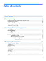
Removal and replacement preliminary requirements 11 Tools required ...11 Service considerations ...11 Plastic parts ...11 Cables and connectors and transporting guidelines 13 Workstation guidelines 13 Equipment guidelines 14 4 Removal and replacement procedures 15 Computer replacement procedures - HP SlateBook 14-p000 | HP SlateBook PC Maintenance and Service Guide - Page 6
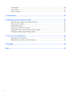
Front speakers ...30 System board ...31 Display assembly ...33 5 Specifications ...40 6 Backing up and recovering your data 41 Updating apps, widgets, and the operating system 41 Backing up and resetting ...41 Resetting factory data ...42 Starting up using the recovery menu 42 Updating the system - HP SlateBook 14-p000 | HP SlateBook PC Maintenance and Service Guide - Page 7
Storage Audio and video Sensors Description HP SlateBook PC NVIDIA® Tegra 4 T40S 1.8-GHz processor (4-plus-1®, quad) NVIDIA Tegra 4, ARM® Cortex-A15 MPCore® Internal graphics: NVIDIA GeForce® GPU with 72 custom cores Supports HD playback, streaming, and HDMI 14.0-in., (1920×1080), BrightView, full - HP SlateBook 14-p000 | HP SlateBook PC Maintenance and Service Guide - Page 8
Serviceability Description Integrated wireless local area network (WLAN) options by way of wireless module One built-in WLAN antenna Supports Miracast Supports a Broadcom BCM4334 802.11abgn 1×1 Wi-Fi + BT 4.0 Combo Adapter HP multiformat Micro Digital - HP SlateBook 14-p000 | HP SlateBook PC Maintenance and Service Guide - Page 9
number (4), and warranty information (5) are located on the bottom of the computer. You may need the information when you travel internationally or when you contact support. Locating the serial number, product number, and model number 3 - HP SlateBook 14-p000 | HP SlateBook PC Maintenance and Service Guide - Page 10
Computer major components 4 Chapter 2 Illustrated parts catalog - HP SlateBook 14-p000 | HP SlateBook PC Maintenance and Service Guide - Page 11
Item (1) (2) (3) (4) (5) Component Spare part number Display assembly: The display assembly is spared at the subcomponent level only. For more display assembly spare part information, see Display assembly subcomponents on page 7. TouchPad (includes cable) 761221-001 Keyboard/top cover ( - HP SlateBook 14-p000 | HP SlateBook PC Maintenance and Service Guide - Page 12
Item (6) (7) (8) (9) (10) (11) (12) Component Spare part number Includes 16-GB of eMMC 759926-001 USB board (includes cable, double-sided adhesive, double-sided adhesive, eSATA port, USB port, and SIM slot) 761218-001 Rear speakers (include left and right rear speakers and cables) 763353-001 - HP SlateBook 14-p000 | HP SlateBook PC Maintenance and Service Guide - Page 13
Display assembly subcomponents Item (1) (2) (3) (4) (5) (6) Component 14-in., LED, FHD, BrightView, TouchScreen display panel: In neon pink finish In sweet yellow finish Antenna Kit, includes WLAN antenna cable and transceiver Webcam/microphone module Display panel cable (includes - HP SlateBook 14-p000 | HP SlateBook PC Maintenance and Service Guide - Page 14
AC adapter (non-PFC, RC, 4.5-mm) HP RJ45-to-USB adapter HP HDMI-to-VGA adapter Power cord (3-pin, black, 1.00-m): For use in Australia For use in Denmark For use in Europe For use in North - HP SlateBook 14-p000 | HP SlateBook PC Maintenance and Service Guide - Page 15
759927-001 759928-001 759930-001 759930-031 759930-051 759930-061 759930-071 759930-161 759930-A41 759930-B31 Description HP RJ45-to-USB adapter HP HDMI-to-VGA adapter 45-W HP Smart AC adapter (non-PFC, RC, 4.5-mm) 3-cell, 32-Wh, 2.96-Ah, Li-ion battery (includes cable) Realtek RTL8723BE 802 - HP SlateBook 14-p000 | HP SlateBook PC Maintenance and Service Guide - Page 16
board (includes cable, eSATA port, USB port, and SIM slot) Power button board (includes cable) TouchPad(includes cable) Display panel in sweet yellow finish (14.0-in., LED, FHD, BrightView, TouchScreen) Webcam/microphone module Display enclosure in neon pink finish Display panel in neon pink finish - HP SlateBook 14-p000 | HP SlateBook PC Maintenance and Service Guide - Page 17
plastic parts. Use care when handling the plastic parts. Apply pressure only at the points designated in the maintenance instructions. Cables and connectors CAUTION: When servicing the computer, be sure that cables are placed in their proper locations during the reassembly process. Improper cable - HP SlateBook 14-p000 | HP SlateBook PC Maintenance and Service Guide - Page 18
touching an electronic component, discharge static electricity by using the guidelines described in this section. Avoid touching pins V 15,000 V 12,000 V 5,000 V 6,000 V 800 V 2,000 V 700 V 11,500 V 4,000 V 14,500 V 5,000 V 26,500 V 20,000 V 21,000 V 11,000 V 55% 7,500 V 3,000 V 400 - HP SlateBook 14-p000 | HP SlateBook PC Maintenance and Service Guide - Page 19
removing items from their containers. ● Always be properly grounded when touching a component or assembly. ● Store reusable ESD-sensitive parts surface and use properly grounded tools and equipment. ● Use conductive field service tools, such as cutters, screw drivers, and vacuums. ● When fixtures - HP SlateBook 14-p000 | HP SlateBook PC Maintenance and Service Guide - Page 20
● Static-dissipative tables or floor mats with hard ties to the ground ● Field service kits ● Static awareness labels ● Material-handling packages ● Nonconductive plastic bags, tubes, mats Voltage protection level 1,500 V 7,500 V 5,000 V 14 Chapter 3 Removal and replacement preliminary requirements - HP SlateBook 14-p000 | HP SlateBook PC Maintenance and Service Guide - Page 21
. For complete and current information on supported parts for your computer, go to http://partsurfer.hp.com, select your country or region, and then follow the on-screen instructions. This chapter provides removal and replacement procedures for authorized service provider only parts. There are as - HP SlateBook 14-p000 | HP SlateBook PC Maintenance and Service Guide - Page 22
3. Remove the 4 rubber feet. NOTE: The front feet (1) and the rear feet (2) are not interchangeable. Make sure to install the computer feet in their proper locations on the computer base enclosure. To install the rubber feet, remove the protective backing from the rubber feet and install them in the - HP SlateBook 14-p000 | HP SlateBook PC Maintenance and Service Guide - Page 23
Keyboard/top cover NOTE: The keyboard/top cover spare part kit includes the keyboard cable. For use in country or region In neon pink finish: For use in Belgium For use in Canada For use in Denmark, Finland, and Norway For use in France For use in Italy In sweet yellow finish: For use in Belgium - HP SlateBook 14-p000 | HP SlateBook PC Maintenance and Service Guide - Page 24
5. Remove the round rubber screw cover (3). NOTE: The oblong rubber screw covers (2) and the round rubber screw cover (3) are not interchangeable. Make sure to install these screw covers in their proper locations on the computer base enclosure. 18 Chapter 4 Removal and replacement procedures - HP SlateBook 14-p000 | HP SlateBook PC Maintenance and Service Guide - Page 25
system board. 13. Release the ZIF connector (5) to which the keyboard cable is attached, and then disconnect the keyboard cable from the system board. 14. Release the ZIF connector (6) to which the TouchPad board cable is attached, and then disconnect the TouchPad board cable from the system board - HP SlateBook 14-p000 | HP SlateBook PC Maintenance and Service Guide - Page 26
the system board components each time the keyboard/top cover is removed. A thermal pad is used on the processor (1) and the heat sink section (2) that services it. 20 Chapter 4 Removal and replacement procedures - HP SlateBook 14-p000 | HP SlateBook PC Maintenance and Service Guide - Page 27
Reverse this procedure to install the keyboard/top cover. TouchPad Component TouchPad (includes cable) Spare part number 761221-001 Before replacing the TouchPad, follow these steps: 1. Turn off the computer. If you are unsure whether the computer is off or in Hibernation, turn the computer on, - HP SlateBook 14-p000 | HP SlateBook PC Maintenance and Service Guide - Page 28
4. Remove the TouchPad (4). Reverse this procedure to install the TouchPad. Power button board Component Power button board (includes cable) Spare part number 761220-001 Before replacing the power button board, follow these steps: 1. Turn off the computer. If you are unsure whether the computer - HP SlateBook 14-p000 | HP SlateBook PC Maintenance and Service Guide - Page 29
3. Remove the power button board (2). Reverse this procedure to install the power button board. WLAN module Component Realtek RTL8723BE 802.11b/g/n 1×1 Wi-Fi + Bluetooth 4.0 Combo Adapter Spare part number 753082-005 Before replacing the WLAN module, follow these steps: 1. Turn off the computer. - HP SlateBook 14-p000 | HP SlateBook PC Maintenance and Service Guide - Page 30
3. Remove the WLAN module (3) by pulling the module away from the slot at an angle. NOTE: If the WLAN antenna cable is not connected to the terminal on the WLAN module, a protective sleeve should be installed on the antenna connector, as shown in the following illustration. Reverse this procedure to - HP SlateBook 14-p000 | HP SlateBook PC Maintenance and Service Guide - Page 31
USB board Component USB board (includes cable, double-sided adhesive, eSATA port, USB port, and SIM slot) Spare part number 761218-001 Before replacing the USB board, follow these steps: 1. Turn off the computer. If you are unsure whether the computer is off or in Hibernation, turn the computer on - HP SlateBook 14-p000 | HP SlateBook PC Maintenance and Service Guide - Page 32
Rear speakers Component Rear speakers (include left and right rear speakers and cables) Spare part number 763353-001 Before replacing the rear speakers, follow these steps: 1. Turn off the computer. If you are unsure whether the computer is off or in Hibernation, turn the computer on, and then - HP SlateBook 14-p000 | HP SlateBook PC Maintenance and Service Guide - Page 33
Power connector cable Component Power connector cable Spare part number 759919-001 Before replacing the power connector cable, follow these steps: 1. Turn off the computer. If you are unsure whether the computer is off or in Hibernation, turn the computer on, and then shut it down through the - HP SlateBook 14-p000 | HP SlateBook PC Maintenance and Service Guide - Page 34
page 17). WARNING! To reduce potential safety issues, use only the battery provided with the computer, a replacement battery provided by HP, or a compatible battery purchased from HP. CAUTION: Removing a battery that is the sole power source for the computer can cause loss of information. To prevent - HP SlateBook 14-p000 | HP SlateBook PC Maintenance and Service Guide - Page 35
4. Remove the battery (4) by sliding it up and forward at an angle. 5. Remove the battery. Reverse this procedure to install the battery. Battery 29 - HP SlateBook 14-p000 | HP SlateBook PC Maintenance and Service Guide - Page 36
Front speakers Component Front speakers (include left and right front speakers and cables) Spare part number 759925-001 Before replacing the front speakers, follow these steps: 1. Turn off the computer. If you are unsure whether the computer is off or in Hibernation, turn the computer on, and then - HP SlateBook 14-p000 | HP SlateBook PC Maintenance and Service Guide - Page 37
Reverse this procedure to install the front speakers. System board NOTE: The system board spare part kit is equipped with a T40S processor, a graphics subsystem with UMA memory, and 2.0-GB of system memory. Component Includes 64-GB of eMMC Includes 32-GB of eMMC Includes 16-GB of eMMC Spare part - HP SlateBook 14-p000 | HP SlateBook PC Maintenance and Service Guide - Page 38
4. Disconnect the power connector cable (4) from the system board. 5. Remove the three Phillips PM1.9×2.8 screws (1) that secure the system board to the base enclosure. 6. Lift the right side of the system board (2) until it rests at an angle. 7. Remove the system board (3) by sliding it up and to - HP SlateBook 14-p000 | HP SlateBook PC Maintenance and Service Guide - Page 39
Display assembly NOTE: The display assembly is spared at the subcomponent level only. For more display assembly spare part information, see the individual removal subsections. Before replacing the display assembly, follow these steps: 1. Turn off the computer. If you are unsure whether the computer - HP SlateBook 14-p000 | HP SlateBook PC Maintenance and Service Guide - Page 40
6. If it is necessary to replace the display panelor any of the display assembly subcomponents: a. Remove the display panel screw covers (1). The display panel screw covers are included in the Rubber Kit, spare part number 759923-001. b. Remove the two Phillips PM1.9×2.1 broad head screws (2) that - HP SlateBook 14-p000 | HP SlateBook PC Maintenance and Service Guide - Page 41
d. Lift the display panel (4) straight up to completely separate the display panel from the display enclosure. CAUTION: Before turning the display panel upside down, make sure the work surface is clear of tools, screws, and any other foreign objects. Failure to follow this caution can result in - HP SlateBook 14-p000 | HP SlateBook PC Maintenance and Service Guide - Page 42
g. Disconnect the display panel cable (3) from the display panel. h. Remove the display panel. The display panel is available using spare part numbers 761504-001 (in neon pink finish) and 761222-001 (in sweet yellow finish). 7. If it is necessary to replace the WLAN antenna cable and transceiver: a. - HP SlateBook 14-p000 | HP SlateBook PC Maintenance and Service Guide - Page 43
b. Release the WLAN antenna cable from the clips (2) built into the right side of the display enclosure. c. Remove the WLAN antenna cable and transceiver. The WLAN antenna cable and transceiver is included in the Antenna Kit, spare part number 761213-001. 8. If it is necessary to replace the webcam/ - HP SlateBook 14-p000 | HP SlateBook PC Maintenance and Service Guide - Page 44
c. Disconnect the webcam/microphone module cable (3) from the webcam/ microphone module. d. Remove the webcam/microphone module. The webcam/microphone module is available using spare part number 761223-001. 9. If it is necessary to replace the display hinges: a. Remove the following screws that - HP SlateBook 14-p000 | HP SlateBook PC Maintenance and Service Guide - Page 45
b. Remove the display hinges and brackets (4). The display hinges are included in the Display Hinge Kit, spare part number 761217-001. Reverse this procedure to reassemble and install the display assembly. Display assembly 39 - HP SlateBook 14-p000 | HP SlateBook PC Maintenance and Service Guide - Page 46
5 Specifications 344 240 15.95 - HP SlateBook 14-p000 | HP SlateBook PC Maintenance and Service Guide - Page 47
system updates automatically and notifies you when it is ready to install the updates. If you want to update the operating system manually, go to http://www.hp.com/ support. You can also set preferences for backing up and restoring your data in case of loss. Backing up and resetting 1. Turn off - HP SlateBook 14-p000 | HP SlateBook PC Maintenance and Service Guide - Page 48
touch the All apps icon, and then touch Settings. 3. Under PERSONAL, touch Backup & reset. 4. Under PERSONAL DATA, select Factory data reset, and then follow the on- screen instructions press the power button. Hold the volume down key until the HP logo is displayed. 3. Move the arrow up or arrow down - HP SlateBook 14-p000 | HP SlateBook PC Maintenance and Service Guide - Page 49
on your computer, and connect to the Internet. 3. To access Settings, touch the All Apps icon, and then touch Settings. 4. Under About SlateBook, touch System updates, and then touch Check now. 5. Follow the on-screen instructions to finish the process. The system may reboot as updates are applied - HP SlateBook 14-p000 | HP SlateBook PC Maintenance and Service Guide - Page 50
7 Power cord set requirements The wide-range input feature of the computer permits it to operate from any line voltage from 100 to 120 volts AC, or from 220 to 240 volts AC. The 3-conductor power cord set included with the computer meets the requirements for use in the country or region where the - HP SlateBook 14-p000 | HP SlateBook PC Maintenance and Service Guide - Page 51
Country/region Accredited agency Applicable note number France UTE 1 Germany VDE 1 Italy IMQ 1 Japan METI 3 The Netherlands KEMA 1 Norway NEMKO 1 The People's Republic of China COC 5 South Korea EK 4 Sweden CEMKO 1 Switzerland SEV 1 Taiwan BSMI 4 The United - HP SlateBook 14-p000 | HP SlateBook PC Maintenance and Service Guide - Page 52
dispose of the battery in general household waste. Follow the local laws and regulations in your area for battery disposal. HP encourages customers to recycle used electronic hardware, HP original print cartridges, and rechargeable batteries. For more information about recycling programs, see the - HP SlateBook 14-p000 | HP SlateBook PC Maintenance and Service Guide - Page 53
1 chipset 1 display panel 1 external media cards 2 graphics 1 memory 1 microphone 1 operating system 2 ports 2 power requirements 2 processors 1 product name 1 sensors 1 serviceability 2 storage 1 video 1 wireless 2 product name 1 R rear speakers removal 26 spare part number 6, 10, 26 Index 47 - HP SlateBook 14-p000 | HP SlateBook PC Maintenance and Service Guide - Page 54
-to-USB adapter, spare part number 8, 9 Rubber Kit, spare part number 6, 8, 9 S Screw Kit, spare part number 8, 9 sensors, product description 1 serviceability, product description 2 speakers removal 26, 30 spare part numbers 6, 9, 10, 26, 30 storage, product description 1 system board removal 31
-
 1
1 -
 2
2 -
 3
3 -
 4
4 -
 5
5 -
 6
6 -
 7
7 -
8
-
9
-
10
-
11
-
12
-
13
-
14
-
15
-
16
-
17
-
18
-
19
-
20
-
21
-
22
-
23
-
24
-
25
-
26
-
27
-
28
-
29
-
30
-
31
-
32
-
33
-
34
-
35
-
36
-
37
-
38
-
39
-
40
-
41
-
42
-
43
-
44
-
45
-
46
-
47
-
48
-
49
-
50
-
51
-
52
-
53
-
54
 |
 |

HP SlateBook PC
Maintenance and Service Guide
IMPORTANT! This document is intended for
HP authorized service providers only.