HP Vectra VE 5/xxx HP Vectra VE 5/xx Series 2 PC Familiarization Guide - D4000 - Page 21
Replacing The Microprocessor - 133
 |
View all HP Vectra VE 5/xxx manuals
Add to My Manuals
Save this manual to your list of manuals |
Page 21 highlights
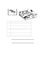
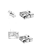
NOTE PCI slots have a 5V supply only, and not a 3.3V supply. Plug and Play The HP Vectra VE 5/xx series 2 PC has a "PnP level 1.0A" BIOS and meets the "Windows 95 Required" level for Plug and Play. Accessory boards which are Plug and Play are automatically configured by the BIOS (Windows 3.11) or by the operating system (Windows 95). All PCI accessory boards are Plug and Play, although not all ISA boards are. Check the accessory board's documentation if you are unsure. Non-Plug and Play in Windows 3.11 To install an ISA accessory board which is not Plug and Play in Windows 3.11, start the ICU program to declare the resources used by the board. To run the ICU: 1 Choose the Plug and Play facility in the Windows Program Manager. 2 Click on the ICU icon to launch the ISA Configuration Utility and configure system resources for the accessory board. The ICU is preloaded with configuration details for many non-Plug and Play accessory boards. If your accessory board is not listed by the ICU, there are two ways you can configure the accessory board: 3 Some non-Plug and Play accessory boards are supplied with a configuration file which can be used by the ICU to determine which resources are required by the board. When prompted by the ICU, insert the diskette containing the configuration file. 4 If there is no configuration file for your accessory board, you will need to enter the configuration details manually when prompted by the ICU. Refer to the documentation supplied with the accessory board for information about the resources the board requires. Non-Plug and Play in Windows 95 To install an ISA accessory board which is not Plug and Play in Windows 95, run the Add New Hardware wizard to configure the accessory. The settings selected by Windows 95 may be different from those recommended by the board's manufacturer. Should this be the case, it might be necessary to alter the board's jumpers. Refer to the documentation supplied with Windows 95 for further details. REPLACING THE MICROPROCESSOR The system board has a ZIF - Zero Insertion Force - "universal" socket to allow the microprocessor to be easily changed. Each microprocessor has a Voltage Regulator Module (VRM) which must be installed with the microprocessor. The 75, 100 and 133 MHz Pentium processors, as mounted in the various models, use the shortening block VRM 5063-7939.
-
 1
1 -
2
-
3
-
4
-
5
-
6
-
7
-
8
-
9
-
10
-
11
-
12
-
13
-
14
-
15
-
 16
16 -
 17
17 -
 18
18 -
 19
19 -
 20
20 -
 21
21 -
 22
22 -
 23
23 -
 24
24 -
 25
25 -
 26
26 -
27
-
28
-
29
 |
 |