HP Z210 HP Workstations - CRU Dataport DX115 kit installation - Page 11
stopped by the release latch as shown in the below.
 |
View all HP Z210 manuals
Add to My Manuals
Save this manual to your list of manuals |
Page 11 highlights
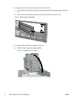
2. Remove and discard the counter-sunk shipping screw at the side of the DX115 case. Figure 15 Removing the shipping screw 3. Install four (supplied) M3 x 5mm screws (black) in the lower four mounting holes. Figure 16 Installing the mounting screws 4. Lift the green release lever for the optical bay and slide the DX115 unit into the bay until it is stopped by the release latch as shown in the figure below. Figure 17 Installing the DX115 case ENWW Step 2-Installing the DX115 case into the optical drive bay 11
-
 1
1 -
2
-
3
-
4
-
5
-
 6
6 -
 7
7 -
 8
8 -
 9
9 -
 10
10 -
 11
11 -
 12
12 -
 13
13 -
 14
14 -
 15
15 -
 16
16 -
17
-
18
-
19
 |
 |

2.
Remove and discard the counter-sunk shipping screw at the side of the DX115 case.
Figure 15
Removing the shipping screw
3.
Install four (supplied) M3 x 5mm screws (black) in the lower four mounting holes.
Figure 16
Installing the mounting screws
4.
Lift the green release lever for the optical bay and slide the DX115 unit into the bay until it is
stopped by the release latch as shown in the figure below.
Figure 17
Installing the DX115 case
ENWW
Step 2—Installing the DX115 case into the optical drive bay
11