HP Z210 HP Workstations - CRU Dataport DX115 kit installation - Page 9
drive cage. The other is part of the chassis frame under the drive cage. Route the data
 |
View all HP Z210 manuals
Add to My Manuals
Save this manual to your list of manuals |
Page 9 highlights
7. Rotate the drive cage to its upright position. Figure 11 Rotating the drive cage up 8. If the cables are not already routed and attached to the system board: a. Connect the SATA data cable to the system board connector labeled SATA1. b. Route the data cable through the cable guides to keep the data cable from being pinched by the drive cage when raising or lowering it. One guide is located on the bottom side of the drive cage. The other is part of the chassis frame under the drive cage. Route the data cable through these guides before connecting it to the optical drive. Figure 12 Routing the drive cable ENWW Step 2-Installing the DX115 case into the optical drive bay 9
-
 1
1 -
2
-
3
-
 4
4 -
 5
5 -
 6
6 -
 7
7 -
 8
8 -
 9
9 -
 10
10 -
 11
11 -
 12
12 -
 13
13 -
 14
14 -
15
-
16
-
17
-
18
-
19
 |
 |

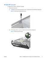
7.
Rotate the drive cage to its upright position.
Figure 11
Rotating the drive cage up
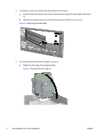
8.
If the cables are not already routed and attached to the system board:
a.
Connect the SATA data cable to the system board connector labeled SATA1.
b.
Route the data cable through the cable guides to keep the data cable from being pinched
by the drive cage when raising or lowering it. One guide is located on the bottom side of the
drive cage. The other is part of the chassis frame under the drive cage. Route the data
cable through these guides before connecting it to the optical drive.
Figure 12
Routing the drive cable
ENWW
Step 2—Installing the DX115 case into the optical drive bay
9