HP Z600 HP Z600 and Z800 Workstations - Sliding rack-mount kit installation - Page 5
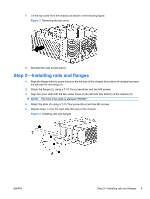
Step 2-Installing rails and flanges
 |
UPC - 884962074053
View all HP Z600 manuals
Add to My Manuals
Save this manual to your list of manuals |
Page 5 highlights
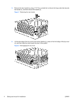
7. Lift the top cover from the chassis as shown in the following figure. Figure 3 Removing the top cover 8. Reinstall the side access panel. Step 2-Installing rails and flanges 1. Align the flange with the screw holes on the left side of the chassis (the bottom of chassis becomes the left side for mounting) (1). 2. Attach the flange (2), using a T-15 Torx screwdriver and two M4 screws. 3. Align the inner slide with the two screw holes on the left side (the bottom) of the chassis (3). NOTE: The front inner slide is stamped "FRONT." 4. Attach the slide (4) using a T-15 Torx screw driver and two M4 screws. 5. Repeat steps 1-4 for the right side (the top) of the chassis. Figure 4 Installing rails and flanges ENWW Step 2-Installing rails and flanges 5
-
 1
1 -
 2
2 -
 3
3 -
 4
4 -
 5
5 -
 6
6 -
 7
7 -
 8
8 -
 9
9 -
 10
10 -
 11
11 -
12
 |
 |
