HP Z6100 HP Designjet Z6100 Printer Series - Setup Poster (60 inch) - Page 8
Important - reel
 |
UPC - 882780989535
View all HP Z6100 manuals
Add to My Manuals
Save this manual to your list of manuals |
Page 8 highlights
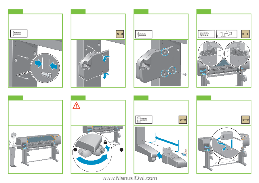
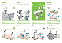
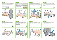
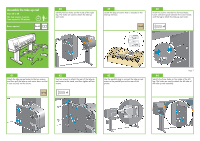
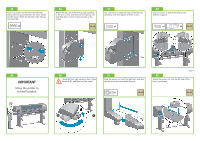
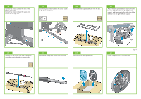
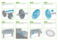
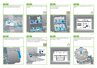
45 Insert two screws into the two forward holes. Leave sufficient space between the screw heads and the leg to attach the left side of the take-up reel assembly. x2 46 Attach the left side of the take-up reel assembly to the two screws, and then pull the take-up reel assembly down so that it rests securely on the screws. 47 Use one screw to attach the rear of the left side assembly, and then tighten all three screws. x1 48 Use four screws to attach the take-up reel deflector supports. x4 x2 49 IMPORTANT Move the printer to its final location. 50 Move the front right wheel so that it faces forward (B), and then lock the wheel. 51 Slide the sensor unit onto the right foot, and then use the screw shown to attach the unit. Page 8 52 Attach the sensor unit onto the left side of the lower cross-brace. x1 A B
-
 1
1 -
2
-
 3
3 -
 4
4 -
 5
5 -
 6
6 -
 7
7 -
 8
8 -
 9
9 -
 10
10 -
 11
11 -
 12
12 -
 13
13 -
14
-
15
-
16
-
17
-
18
-
19
-
20
-
21
-
22
 |
 |