HP dx2818 Hardware Reference Guide - dx2818 Microtower Model
HP dx2818 - Microtower PC Manual
 |
View all HP dx2818 manuals
Add to My Manuals
Save this manual to your list of manuals |
HP dx2818 manual content summary:
- HP dx2818 | Hardware Reference Guide - dx2818 Microtower Model - Page 1
Hardware Reference Guide - dx2818 Microtower Model HP Compaq Business PC - HP dx2818 | Hardware Reference Guide - dx2818 Microtower Model - Page 2
HP products and services are set forth in the express warranty statements accompanying such products and services. Nothing herein should be construed as constituting an additional warranty. HP Company. Hardware Reference Guide HP Compaq Business PC dx2818 Mictower Model First Edition (October - HP dx2818 | Hardware Reference Guide - dx2818 Microtower Model - Page 3
About This Book This guide provides basic information for upgrading this computer model. WARNING! Text set off in this manner indicates that failure to follow directions could result in bodily - HP dx2818 | Hardware Reference Guide - dx2818 Microtower Model - Page 4
iv About This Book ENWW - HP dx2818 | Hardware Reference Guide - dx2818 Microtower Model - Page 5
Table of contents 1 Product Features Standard Configuration Features ...1 Serviceability Features ...1 Front Panel Components ...2 Rear Panel Components ...3 Keyboard ...4 Using the Windows Logo Key 4 Serial Number Location ...6 2 Hardware Upgrades Warnings and Cautions ...7 Removing the Computer - HP dx2818 | Hardware Reference Guide - dx2818 Microtower Model - Page 6
Appendix B Battery Replacement Appendix C External Security Devices Installing a Security Lock ...42 Cable Lock ...42 Padlock ...43 HP Business PC Security Lock 43 Hood Sensor ...45 Port Cover ...45 Appendix D Electrostatic Discharge Preventing Electrostatic Damage ...47 Grounding Methods ...47 - HP dx2818 | Hardware Reference Guide - dx2818 Microtower Model - Page 7
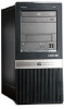
only). Instructions for using the utility are provided in the Troubleshooting Guide. Figure 1-1 HP Compaq dx2818 Microtower NOTE: The drive configuration shown above may be different than your computer model. The illustration shown above may look different than your computer model. Serviceability - HP dx2818 | Hardware Reference Guide - dx2818 Microtower Model - Page 8
Front Panel Components Drive configuration may vary by model. Figure 1-2 Front Panel Components Table 1-1 Front Panel Components 1 5.25-inch Optical Drives1 6 Hard Drive Activity Light 2 Optical Drive Activity Light 7 Optical Drive Eject Button 3 Diskette Drive (optional)2 8 USB ( - HP dx2818 | Hardware Reference Guide - dx2818 Microtower Model - Page 9
to be changed in Computer Setup to use both connectors. For information about setting the boot VGA controller, refer to the Computer Setup (F10) Utility Guide. ENWW Rear Panel Components 3 - HP dx2818 | Hardware Reference Guide - dx2818 Microtower Model - Page 10
Keyboard Figure 1-4 Keyboard Components Table 1-3 Keyboard Components 1 Function Keys Perform special functions depending on the software application being used. 2 Editing Keys Include the following: Insert, Home, Page Up, Delete, End, and Page Down. 3 Status Lights Indicate the status of the - HP dx2818 | Hardware Reference Guide - dx2818 Microtower Model - Page 11
Table 1-4 Windows Logo Key Functions (continued) Windows Logo Key + f Launches Find Document Windows Logo Key + Ctrl + f Launches Find Computer Windows Logo Key + F1 Launches Windows Help Windows Logo Key + l Locks the computer if you are connected to a network domain, or allows you to - HP dx2818 | Hardware Reference Guide - dx2818 Microtower Model - Page 12
a unique serial number and product ID number that are located on the top of the computer. Keep these numbers available for use when contacting customer service for assistance. Figure 1-5 Serial Number and Product ID Location 6 Chapter 1 Product Features ENWW - HP dx2818 | Hardware Reference Guide - dx2818 Microtower Model - Page 13
be sure to carefully read all of the applicable instructions, cautions, and warnings in this guide. WARNING! To reduce the risk of personal injury important electrical and mechanical safety information. This guide is located on the Web at http://www.hp.com/ergo. WARNING! Energized and moving parts - HP dx2818 | Hardware Reference Guide - dx2818 Microtower Model - Page 14
Removing the Computer Access Panel 1. Remove/disengage any security devices that prohibit opening the computer. 2. Remove all removable media, such as diskettes or compact discs, from the computer. 3. Turn off the computer properly through the operating system, then turn off any external devices. 4. - HP dx2818 | Hardware Reference Guide - dx2818 Microtower Model - Page 15
Replacing the Computer Access Panel Place the access panel on the chassis with about 1.3 cm (1/2 inch) of the panel hanging off the back of the chassis and slide it into place (1). Ensure that the hole for the thumbscrew is aligned with the hole in the chassis and tighten the thumbscrew (2). Figure - HP dx2818 | Hardware Reference Guide - dx2818 Microtower Model - Page 16
Removing the Front Bezel 1. Remove/disengage any security devices that prohibit opening the computer. 2. Remove all removable media, such as diskettes or compact discs, from the computer. 3. Turn off the computer properly through the operating system, then turn off any external devices. 4. - HP dx2818 | Hardware Reference Guide - dx2818 Microtower Model - Page 17
before installing a drive. To remove a bezel blank: 1. Follow the instructions described in Removing the Front Bezel on page 10. 2. To remove the to be replaced at a later date, you can order a replacement blank from HP. 3. To remove the 3.5-inch bezel blank, press the two retaining tabs towards - HP dx2818 | Hardware Reference Guide - dx2818 Microtower Model - Page 18
Replacing the Front Bezel Insert the three hooks on the left side of the bezel into the slots on the chassis (1) and rotate the bezel on from left to right (2) so that it snaps in place. Figure 2-5 Replacing the Front Bezel 12 Chapter 2 Hardware Upgrades ENWW - HP dx2818 | Hardware Reference Guide - dx2818 Microtower Model - Page 19
populated with up to four industry-standard DIMMs. These memory sockets are populated with at least one preinstalled DIMM. To achieve the maximum memory support, you can populate the system board with up to 8-GB of memory configured in a highperforming dual channel mode. DDR2-SDRAM DIMMs For proper - HP dx2818 | Hardware Reference Guide - dx2818 Microtower Model - Page 20
Populating DIMM Sockets There are four DIMM sockets on the system board, with two sockets per channel. The sockets are labeled XMM1, XMM2, XMM3, and XMM4. Sockets XMM1 and XMM2 operate in memory channel A. Sockets XMM3 and XMM4 operate in memory channel B. Figure 2-6 DIMM Socket Locations Table 2-1 - HP dx2818 | Hardware Reference Guide - dx2818 Microtower Model - Page 21
with the least amount of memory describes the total amount of memory assigned to dual channel and the remainder is assigned to single channel. For optimal speed, the channels should be balanced so that the largest amount of memory is spread between the two channels. If one channel will have more - HP dx2818 | Hardware Reference Guide - dx2818 Microtower Model - Page 22
7. Open both latches of the memory module socket (1), and insert the memory module into the socket (2). Figure 2-7 Installing a DIMM NOTE: A memory module can be installed in only one way. Match the notch on the module with the tab on the memory socket. A DIMM must occupy the XMM1 socket. Always - HP dx2818 | Hardware Reference Guide - dx2818 Microtower Model - Page 23
Removing or Installing an Expansion Card The computer has two standard PCI expansion slots, one PCI Express x1 expansion slot, and one PCI Express x16 expansion slot. The expansion slots accommodate full-height or half-height expansion cards. Figure 2-8 Expansion Slot Locations Table 2-2 Expansion - HP dx2818 | Hardware Reference Guide - dx2818 Microtower Model - Page 24
5. Remove the computer access panel. 6. Locate the correct vacant expansion socket on the system board and the corresponding expansion slot on the back of the computer chassis. 7. On the rear of the computer, a slot cover lock secures the expansion card brackets in place. Remove the screw from the - HP dx2818 | Hardware Reference Guide - dx2818 Microtower Model - Page 25
NOTE: Before removing an installed expansion card, disconnect any cables that may be attached to the expansion card. a. If you are installing an expansion card in a vacant socket, you must use a flatblade screwdriver to pry out the metal shield on the rear panel that covers the expansion slot. Be - HP dx2818 | Hardware Reference Guide - dx2818 Microtower Model - Page 26
c. If you are removing a PCI Express x16 card, pull the retention arm on the back of the expansion socket away from the card and carefully rock the card back and forth until the connectors pull free from the socket. Be sure not to scrape the card against the other components. Figure 2-12 Removing a - HP dx2818 | Hardware Reference Guide - dx2818 Microtower Model - Page 27
11. To install a new expansion card, hold the card just above the expansion socket on the system board then move the card toward the rear of the chassis so that the bottom of the bracket on the card slides into the small slot on the chassis. Press the card straight down into the expansion socket on - HP dx2818 | Hardware Reference Guide - dx2818 Microtower Model - Page 28
were disengaged when the access panel was removed. 17. Reconfigure the computer, if necessary. Refer to the Computer Setup (F10) Utility Guide for instructions on using Computer Setup. Drive Positions Figure 2-15 Drive Positions 1 Two 5.25-inch external drive bays for optional drives (optical drive - HP dx2818 | Hardware Reference Guide - dx2818 Microtower Model - Page 29
media card reader to the USB connector labeled F_USB2. ● The system does not support Parallel ATA (PATA) optical drives or PATA hard drives. ● You may install use M3 metric screws. The HP-supplied 6-32 standard screws (1) are silver. The HP-supplied M3 metric guide screws (2) are black. Figure - HP dx2818 | Hardware Reference Guide - dx2818 Microtower Model - Page 30
CAUTION: To prevent loss of work and damage to the computer or drive: If you are inserting or removing a drive, shut down the operating system properly, turn off the computer, and unplug the power cord. Do not remove a drive while the computer is on or in standby mode. Before handling a drive, - HP dx2818 | Hardware Reference Guide - dx2818 Microtower Model - Page 31
Table 2-3 System Board Drive Connections (continued) No. System Board Connector System Board Label 5 SATA4 SATA4 6 Diskette Drive FLOPPY Color orange black Removing an Optical Drive CAUTION: All removable media should be taken out of a drive before removing the drive from the computer. To - HP dx2818 | Hardware Reference Guide - dx2818 Microtower Model - Page 32
7. Remove the two screws that secure the drive to the drive cage (1), then slide the drive out of the front of the chassis (2). Figure 2-19 Removing the Optical Drive NOTE: To install an optical drive, refer to Installing an Optical Drive into the 5.25-inch Drive Bay on page 26. Installing an - HP dx2818 | Hardware Reference Guide - dx2818 Microtower Model - Page 33
9. Slide the drive in through the front of the chassis (1) until the screw holes on the drive are aligned with the screw holes on the drive cage and install the two M3 metric retainer screws (2) as shown in the following illustration. NOTE: Extra drive retainer screws are provided on the interior of - HP dx2818 | Hardware Reference Guide - dx2818 Microtower Model - Page 34
The system automatically recognizes the drive and reconfigures the computer. Removing an External 3.5-inch Drive CAUTION: All removable media should be taken out of a drive before removing the drive from the computer. NOTE: The 3.5-inch drive bay may contain a diskette drive or a media card reader. - HP dx2818 | Hardware Reference Guide - dx2818 Microtower Model - Page 35
7. Remove the two retainer screws that secure the drive to the bay (1) then slide the drive forward and out of the bay (2). Figure 2-23 Removing a 3.5-inch Device (Diskette Drive Shown) NOTE: To install an external 3.5-inch drive, refer to Installing a Drive into the 3.5-inch External Drive Bay on - HP dx2818 | Hardware Reference Guide - dx2818 Microtower Model - Page 36
Recovery Disc Set to restore the operating system, software drivers, and any software applications that were preinstalled on the computer. If you do not have this CD set, select Start > HP Backup and Recovery and create it now. 1. Remove/disengage any security devices - HP dx2818 | Hardware Reference Guide - dx2818 Microtower Model - Page 37
3. Turn off the computer properly through the operating system, then turn off any external devices. 4. Disconnect the power cord from the power outlet and disconnect any external devices. CAUTION: Regardless of the power-on state, voltage is always present on the system board as long as the system - HP dx2818 | Hardware Reference Guide - dx2818 Microtower Model - Page 38
8. Lift the hard drive cage out of the chassis. Figure 2-27 Removing the Hard Drive Cage 9. Disconnect the power cable (1) and data cable (2) from the back of the hard drive. Figure 2-28 Disconnecting the Hard Drive Cables 32 Chapter 2 Hardware Upgrades ENWW - HP dx2818 | Hardware Reference Guide - dx2818 Microtower Model - Page 39
10. Remove the four screws that secure the hard disk drive to the hard drive cage (1), then slide the hard disk drive out of the hard drive cage (2). Figure 2-29 Removing the Hard Drive NOTE: To install an internal 3.5-inch hard drive, refer to Installing an Internal 3.5-inch Hard Drive on page 33. - HP dx2818 | Hardware Reference Guide - dx2818 Microtower Model - Page 40
2. Slide the new drive into the hard drive cage (1), aligning the drive with the four screw holes on the cage. Install the four 6-32 standard screws that secure the hard disk drive to the hard drive cage (2). Make sure the hard disk drive cables are facing the top of the drive cage. NOTE: If you are - HP dx2818 | Hardware Reference Guide - dx2818 Microtower Model - Page 41
3. Connect the power cable (1) and data cable (2) to the back of the hard drive. Figure 2-31 Connecting the Hard Drive Cables CAUTION: Never crease or bend a SATA data cable tighter than a 30 mm (1.18 in) radius. A sharp bend can break the internal wires. 4. Place the hard drive cage into the - HP dx2818 | Hardware Reference Guide - dx2818 Microtower Model - Page 42
to the dark blue connector labeled SATA1 to avoid any hard drive performance problems. If you are adding a second hard drive, connect the data cable to Set to restore the operating system, software drivers, and any software applications that were preinstalled on the computer. 36 - HP dx2818 | Hardware Reference Guide - dx2818 Microtower Model - Page 43
A Specifications Table A-1 Specifications Desktop Dimensions Height 15.12 in 384 mm Width 7.26 in 184.5 mm Depth 15.83 in 402 mm Approximate Weight 18.4 lb 8.34 kg Temperature Range Operating (35C) 50° to 95°F 10° to 35°C Nonoperating -22° to 149°F -30° to 65°C Relative - HP dx2818 | Hardware Reference Guide - dx2818 Microtower Model - Page 44
Table A-1 Specifications (continued) Rated Input Current (maximum)1 8A @ 115 VAC 4A @ 230 VAC 1 This system utilizes a passive power factor corrected power supply. The power factor correction is present in the 230V operating mode only. This allows the system to pass the CE mark requirements for - HP dx2818 | Hardware Reference Guide - dx2818 Microtower Model - Page 45
, or dispose of in fire or water. Replace the battery only with the HP spare designated for this product. CAUTION: Before replacing the battery, it is important will be cleared. Refer to the Computer Setup (F10) Utility Guide for information on backing up the CMOS settings. Static electricity can - HP dx2818 | Hardware Reference Guide - dx2818 Microtower Model - Page 46
an internal component to gain access to the battery. 7. Depending on the type of battery holder on the system board, complete the following instructions to replace the battery. Type 1 a. Lift the battery out of its holder. Figure B-1 Removing a Coin Cell Battery (Type 1) b. Slide the replacement - HP dx2818 | Hardware Reference Guide - dx2818 Microtower Model - Page 47
the computer. 10. Reset the date and time, your passwords, and any special system setups using Computer Setup. Refer to the Computer Setup (F10) Utility Guide. 11. Lock any security devices that were disengaged when the access panel was removed. ENWW 41 - HP dx2818 | Hardware Reference Guide - dx2818 Microtower Model - Page 48
C External Security Devices NOTE: For information on data security features, refer to the Computer Setup (F10) Utility Guide and the Desktop Management Guide. Installing a Security Lock The security locks displayed below and on the following pages can be used to secure the computer. Cable Lock - HP dx2818 | Hardware Reference Guide - dx2818 Microtower Model - Page 49
Padlock Figure C-2 Installing a Padlock HP Business PC Security Lock 1. Fasten the security cable by looping it around a stationary object. Figure C-3 Securing the Cable to a Fixed Object ENWW Installing a Security Lock 43 - HP dx2818 | Hardware Reference Guide - dx2818 Microtower Model - Page 50
2. Thread the keyboard and mouse cables through the lock. Figure C-4 Threading the Keyboard and Mouse Cables 3. Screw the lock to the chassis using the screw provided. Figure C-5 Attaching the Lock to the Chassis 44 Appendix C External Security Devices ENWW - HP dx2818 | Hardware Reference Guide - dx2818 Microtower Model - Page 51
4. Insert the plug end of the security cable into the lock (1) and push the button in (2) to engage the lock. Use the key provided to disengage the lock. Figure C-6 Engaging the Lock Hood Sensor The hood sensor will sound an alarm if the access panel is removed while there is still power to the - HP dx2818 | Hardware Reference Guide - dx2818 Microtower Model - Page 52
46 Appendix C External Security Devices ENWW - HP dx2818 | Hardware Reference Guide - dx2818 Microtower Model - Page 53
mat. If you do not have any of the suggested equipment for proper grounding, contact an HP authorized dealer, reseller, or service provider. NOTE: For more information on static electricity, contact an HP authorized dealer, reseller, or service provider. ENWW Preventing Electrostatic Damage 47 - HP dx2818 | Hardware Reference Guide - dx2818 Microtower Model - Page 54
E Computer Operating Guidelines, Routine Care and Shipping Preparation Computer Operating Guidelines and Routine Care Follow these guidelines to properly set up and care for the computer and monitor: ● Keep the computer away from excessive moisture, direct sunlight, and extremes of heat and cold. ● - HP dx2818 | Hardware Reference Guide - dx2818 Microtower Model - Page 55
the finish. Safety If any object or liquid falls into the drive, immediately unplug the computer and have it checked by an authorized HP service provider. Shipping Preparation Follow these suggestions when preparing to ship the computer: 1. Back up the hard drive files on PD discs, tape cartridges - HP dx2818 | Hardware Reference Guide - dx2818 Microtower Model - Page 56
13 optical drive 26 security locks 42 K keyboard components 4 connector 3 L line-in connector 3 line-out connector 3 locks cable lock 42 50 Index HP Business PC Security Lock 43 padlock 43 M media card reader installing 29 removing 28 memory installing 13 populating sockets 14 specifications 13 - HP dx2818 | Hardware Reference Guide - dx2818 Microtower Model - Page 57
19 PCI Express x16 card 20 reset button 2 S security cable lock 42 hood sensor 45 HP Business PC Security Lock 43 padlock 43 port cover 45 serial number location 6 serial port 3 serviceability features 1 shipping preparation 49 specifications computer 37 memory 13 system board drive connections 24
-
 1
1 -
 2
2 -
 3
3 -
 4
4 -
 5
5 -
 6
6 -
 7
7 -
8
-
9
-
10
-
11
-
12
-
13
-
14
-
15
-
16
-
17
-
18
-
19
-
20
-
21
-
22
-
23
-
24
-
25
-
26
-
27
-
28
-
29
-
30
-
31
-
32
-
33
-
34
-
35
-
36
-
37
-
38
-
39
-
40
-
41
-
42
-
43
-
44
-
45
-
46
-
47
-
48
-
49
-
50
-
51
-
52
-
53
-
54
-
55
-
56
-
57
 |
 |

Hardware Reference Guide - dx2818
Microtower Model
HP Compaq Business PC