HP dx2818 Hardware Reference Guide - dx2818 Microtower Model - Page 20
Populating DIMM Sockets, labeled XMM1, XMM2
 |
View all HP dx2818 manuals
Add to My Manuals
Save this manual to your list of manuals |
Page 20 highlights
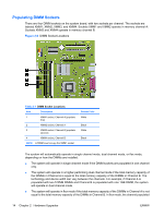
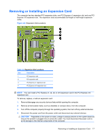
Populating DIMM Sockets There are four DIMM sockets on the system board, with two sockets per channel. The sockets are labeled XMM1, XMM2, XMM3, and XMM4. Sockets XMM1 and XMM2 operate in memory channel A. Sockets XMM3 and XMM4 operate in memory channel B. Figure 2-6 DIMM Socket Locations Table 2-1 DIMM Socket Locations Item Description 1 XMM1 socket, Channel A (populate first) 2 XMM2 socket, Channel A 3 XMM3 socket, Channel B (populate second) 4 XMM4 socket, Channel B NOTE: A DIMM must occupy the XMM1 socket. Socket Color White Black White Black The system will automatically operate in single channel mode, dual channel mode, or flex mode, depending on how the DIMMs are installed. ● The system will operate in single channel mode if the DIMM sockets are populated in one channel only. ● The system will operate in a higher-performing dual channel mode if the total memory capacity of the DIMMs in Channel A is equal to the total memory capacity of the DIMMs in Channel B. The technology and device width can vary between the channels. For example, if Channel A is populated with two 512MB DIMMs and Channel B is populated with one 1GB DIMM, the system will operate in dual channel mode. ● The system will operate in flex mode if the total memory capacity of the DIMMs in Channel A is not equal to the total memory capacity of the DIMMs in Channel B. In flex mode, the channel populated 14 Chapter 2 Hardware Upgrades ENWW
-
 1
1 -
2
-
3
-
4
-
5
-
6
-
7
-
8
-
9
-
10
-
11
-
12
-
13
-
14
-
 15
15 -
 16
16 -
 17
17 -
 18
18 -
 19
19 -
 20
20 -
 21
21 -
 22
22 -
 23
23 -
 24
24 -
 25
25 -
26
-
27
-
28
-
29
-
30
-
31
-
32
-
33
-
34
-
35
-
36
-
37
-
38
-
39
-
40
-
41
-
42
-
43
-
44
-
45
-
46
-
47
-
48
-
49
-
50
-
51
-
52
-
53
-
54
-
55
-
56
-
57
 |
 |
