Hitachi C12RSH User Guide - Page 57
Adjusting The Power Tool Prior To Use - saw
 |
UPC - 717709010345
View all Hitachi C12RSH manuals
Add to My Manuals
Save this manual to your list of manuals |
Page 57 highlights
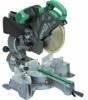
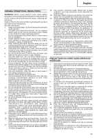
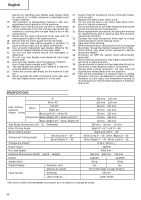
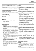
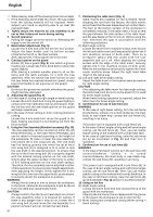
English STANDARD ACCESSORIES (1) 305 mm TCT Saw blade (mounted on tool 1 (2) Dust bag 1 (3) 17 mm Box wrench 1 (4) Vise Assembly 1 (5) Holder 1 Standard accessories are subject to change without notice. OPTIONAL ACCESSORIES (SOLD SEPARATELY) (1) Extension Holder and Stopper (2) Crown molding Vise Ass'y (Include Crown molding Stopper (L)) (3) Crown molding Stopper (L) (4) Crown molding Stopper (R) Optional accessories are subject to change without notice. APPLICATION ⅜ Cutting various types of aluminium sash and wood. UNPACKING ⅜ Carefully unpack the power tool and all related items (standard accessories). ⅜ Check carefully to make certain all related items (standard accessories) are present. PRIOR TO OPERATION 1. Power source Ensure that the power source to be utilized conforms to the power requirements specified on the product nameplate. 2. Power switch Ensure that the power switch is in the OFF position. If the plug is connected to a receptacle while the trigger switch is in the ON position, the power tool will start operating immediately, inviting serious accident. 3. Extention cord When the work area is removed from the power source, use an extension cord of sufficient thickness and rated capacity. The extension cord should be kept as short as practicable. 4. When the power tool is prepared for shipping, its main parts are secured by a locking pin Move the handle slightly so that the locking pin can be disengaged. During transport, lock the locking pin into the gear case (Fig. 3). 5. Attach the dust bag to the main unit (Fig. 1) 6. Installation Ensure that the machine is always fixed to bench. Attach the power tool to a level, horizontal work bench. Select 8 mm diameter bolts suitable in length for the thickness of the work bench. Bolt length should be at least 40 mm plus the thickness of the work bench. For example, use 8 mm × 65 mm bolts for a 25 mm thick work bench. ADJUSTING THE POWER TOOL PRIOR TO USE CAUTION Make all necessary adjustments before inserting the plug in the power source. 1. Check to see that the lower guard operates smoothly CAUTION ⅜ This slide compound miter saw is equipped with a saw head lock as safety device. ⅜ To lower the saw head to cut, the lock must be released by pressing the lever (A) with your thumb. (1) When you push down the handle while pushing the lever (A), check that the lower guard revolves smoothly (Fig. 4). (2) Next, check that the lower guard returns to the original position when the handle is raised. 2. Checking the saw blade lower limit position (Fig. 5 and Fig. 6) Check that the saw blade can be lowered 9 mm to 10 mm below the table insert. When you replace a saw blade with a new one, adjust the lower limit position so that the saw blade will not cut the turntable or complete cutting cannot be done. To adjust the lower limit position of the saw blade, follow the procedure (1) indicated below. (Fig. 6) Furthermore, when changing the position of a 8 mm depth adjustment bolt that serves as a lower limit position stopper of the saw blade. (1) Turn the 8 mm depth adjustment bolt, change the height where the bolt head and the hinge contacts, and adjust the lower limit position of the saw blade. NOTE Confirm that the saw blade is adjusted so that it will not cut into the turntable. 3. Lower limit position of saw blade when cutting a large workpiece NOTE When cutting a workpiece exceeding 107 mm in height in right-angle cutting or 70 mm in left bevel angle cutting or 45 mm in right bevel angle cutting, adjust the lower limit position so that the base of the motor head (Fig. 5) will not come in contact with the workpiece. To adjust the lower limit position of the saw blade, follow the procedure (1) shown in Fig. 5. (1) Lower the motor head, and turn the 8 mm depth adjustment bolt and make adjustments so that there can be a clearance of 2 mm to 3 mm between the lower limit position of the motor head and the top of the workpiece at the saw blade's lower limit position where the head of the 8 mm depth adjustment bolt contacts the hinge. PRACTICAL APPLICATIONS WARNING ⅜ To avoid personal injury, never remove or place a workpiece on the table while the tool is being operated. ⅜ Never place your limbs inside of the line next to warning sign while the tool is being operated. This may cause hazardous conditions (see Fig. 8). CAUTION ⅜ It is dangerous to remove or install the workpiece while the saw blade is turning. 56
-
 1
1 -
2
-
3
-
4
-
5
-
6
-
7
-
8
-
9
-
10
-
11
-
12
-
13
-
14
-
15
-
16
-
17
-
18
-
19
-
20
-
21
-
22
-
23
-
24
-
25
-
26
-
27
-
28
-
29
-
30
-
31
-
32
-
33
-
34
-
35
-
36
-
37
-
38
-
39
-
40
-
41
-
42
-
43
-
44
-
45
-
46
-
47
-
48
-
49
-
50
-
51
-
 52
52 -
 53
53 -
 54
54 -
 55
55 -
 56
56 -
 57
57 -
 58
58 -
 59
59 -
 60
60 -
 61
61 -
 62
62 -
63
-
64
-
65
-
66
-
67
-
68
-
69
-
70
-
71
-
72
-
73
-
74
 |
 |