Hitachi C12RSH User Guide - Page 61
Bevel angle fine adjustment - square cuts
 |
UPC - 717709010345
View all Hitachi C12RSH manuals
Add to My Manuals
Save this manual to your list of manuals |
Page 61 highlights
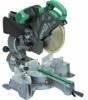
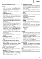
English counterclockwise, allows fine adjustment of the turntable to the left. (3) After adjusting to the desired angle, tighten the side handle. CAUTION Always check that the side handle is secured and the turntable is clamped. If you attempt angle cutting without clamping the turntable, then the turntable might shift unexpectedly causing injuries. 18. Bevel cutting procedures CAUTION ⅜ Ensure that the clamp lever is securely fixed when beveling. ⅜ Please do this if the length of the material being cut off is more than 25 mm long. Sometimes cutting cannot be accomplished because the saw blade will catch on the inside of the lower guard. (1) Loosen the clamp lever and bevel the saw blade to the left or to the right. When tilting the motor head to the right pull the set pin (A) towards the rear. The clamp lever adopts a latchet system. When contacting the work bench and the main body, pull the clamp lever in the direction of the arrow mark as illustrated in Fig. 24, and change the direction of the clamp lever. (2) Adjust the bevel angle to the desired setting while watching the bevel angle scale and indicator, then secure the clamp lever. WARNING ⅜ When the workpiece is secured on the left or right side of the blade, the short cut-off portion will come to rest on the right or left side of the saw blade. Always turn the power off and let the saw blade stop completely before raising the handle from the workpiece. If the handle is raised while the saw blade is still rotating, the cut-off piece may become jammed against the saw blade causing fragments to scatter about dangerously. ⅜ When stopping the bevel cutting operation halfway, start cutting after pulling back the motor head to the initial position. Starting from halfway, without pulling back, causes the lower guard to be caught in the cutting groove of the workpiece and to contact the saw blade. CAUTION When cutting a workpiece of 75 mm height in the left 45° bevel cutting position or a workpiece of 50 mm height in the right 45° bevel cutting position, adjust the lower limit position of the motor head so that the gap between the lower edge of the motor head and the workpiece will be 2 to 3 mm at the lower limit position (refer to "2. Checking the saw blade lower limit position" on page 56). 19. Bevel angle fine adjustment (1) Grip the handle on the motor head and position it at the bevel angle you need. Temporarily tighten the clamp lever (Fig. 25). CAUTION If not tightened firmly enough the motor head might suddenly move or slip, causing injuries. Be sure to tighten the motor head section enough so it will not move. (2) When making fine adjustments of the bevel angle, turn the knob (B) while supporting the handle with your hand (Fig. 26). NOTE Turning knob (B) clockwise, allows fine adjustment of the main unit to the left (as seen from front). Turning knob (B) counterclockwise, allows fine adjustment of the main unit to the right (as seen from front). (3) After adjusting to the desired angle, tighten the clamp lever and clamp the motor head. CAUTION Always check that the clamp lever is secured and the motor head is clamped. If you attempt angle cutting without clamping the motor head, then the motor head might shift unexpectedly causing injuries. 20. Compound cutting procedures Compound cutting can be performed by following the instructions in 16 and 18 above. For maximum dimensions for compound cutting, refer to "SPECIFICATIONS" table. CAUTION Always secure the workpiece with the right or left hand and cut it by sliding the round portion of the saw backwards with the left hand. It is very dangerous to rotate the turntable to the left during compound cutting because the saw blade may come into contact with the hand that is securing the workpiece. In case of compound cutting (angle + bevel) by left bevel, turn the sub-fence (B) counterclockwise, and engage in the cutting operation. In case of compound cutting (angle + bevel) by right bevel, turn the sub-fence (A) clockwise, and engage in the cutting operation. 21. Cutting long materials When cutting long materials, use an auxiliary platform which is the same height as the holder (optional accessory) and base of the special auxiliary equipment. Capacity: wooden material (W × H × L) 300 mm × 45 mm × 1300 mm, or 180 mm × 25 mm × 2000 mm 22. Installing the holders ... (Optional accessory) The holders help keep longer workpieces stable and in place during the cutting operation. (1) As indicated in Fig. 27, use a steel square for aligning the upper edge of the holders with the base surface. Loosen the 6 mm wing nut. Turn a height adjustment bolt 6 mm, and adjust the height of the holder. (2) After adjustment, firmly tighten the 6 mm wing nut and fasten the holder with the 6 mm knob bolt (optional accessory). If the length of Height Adjustment Bolt 6 mm is insufficient, spread a thin plate beneath. Make sure the end of Height Adjustment Bolt 6 mm does not protrude from the holder. CAUTION ⅜ When transporting or carrying the tool, do not grasp the holder. ⅜ There is the danger of the holder slipping out of the base. Grasp the handle instead of the holder. 23. Stopper for precision cutting ... (Stopper and holder are optional accessory) The stopper facilitates continuous precision cutting in lengths of 285 mm to 450 mm. 60
-
 1
1 -
2
-
3
-
4
-
5
-
6
-
7
-
8
-
9
-
10
-
11
-
12
-
13
-
14
-
15
-
16
-
17
-
18
-
19
-
20
-
21
-
22
-
23
-
24
-
25
-
26
-
27
-
28
-
29
-
30
-
31
-
32
-
33
-
34
-
35
-
36
-
37
-
38
-
39
-
40
-
41
-
42
-
43
-
44
-
45
-
46
-
47
-
48
-
49
-
50
-
51
-
52
-
53
-
54
-
55
-
 56
56 -
 57
57 -
 58
58 -
 59
59 -
 60
60 -
 61
61 -
 62
62 -
 63
63 -
 64
64 -
 65
65 -
 66
66 -
67
-
68
-
69
-
70
-
71
-
72
-
73
-
74
 |
 |