Hitachi C12RSH User Guide - Page 58
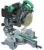
Using the Vise Assembly Standard accessory Fig. 10 - miter saw
 |
UPC - 717709010345
View all Hitachi C12RSH manuals
Add to My Manuals
Save this manual to your list of manuals |
Page 58 highlights
English ⅜ When sawing, clean off the shavings from the turntable. ⅜ If the shavings accumulate too much, the saw blade from the cutting material will be exposed. Never subject your hand or anything else to go near the exposed blade. 1. Tightly secure the material by vise assembly to be cut so that it does not move during cutting 2. Switch operation Pulling the trigger turns the switch on. Releasing the trigger turns the switch off. 3. Base holder adjustment (Fig. 8) Loosen the 6 mm bolt with the 10 mm box wrench. Adjust the base holder until its bottom surface contacts the bench or the floor surface. After adjustment, firmly tighten the 6 mm bolt. 4. Cutting a groove on the guard Holder (A) has a guard (Fig. 9) into which a groove must be cut. Loosen the 6 mm knob bolt to retract the guard slightly. After placing a suitable wooden piece to sit on the fence and the table surfaces, fix it with the vise assembly. After the switch has been turned on and the saw blade has reached maximum speed, slowly lower the handle to cut a groove on the guard. CAUTION Do not cut the groove too quickly; otherwise the guard might become damaged. 5. Adjusting the guard (Fig. 9) (1) In the case of cutting at a right angle or bevel cutting: Loosen the 6 mm knob bolt, bring the guard lightly in contact with the materials to be cut and secure. Align the ink line with the saw blade groove on the guard and begin operations. (2) In the case of miter cutting or miter cutting plus bevel cutting: Loosen the 6 mm knob bolt, move the guard to the back, making sure that it is not sticking out from the fence surface. 6. Using the Vise Assembly (Standard accessory) (Fig. 10) The vise assembly can be mounted on either the left fence (Fence (B)), or the right fence (Fence(A)), and can be raised or lowered according to the height of the workpiece. To raise or lower the vise assembly, first loosen the 6 mm wing bolt (A). The vise shaft has five locking grooves into which the tip of the 6 mm wing bolt (A) is designed to fit in order to lock the vise shaft in the desired position. To ensure that the tip of the 6 mm wing bolt (A) is properly aligned with the desired locking groove on the vise shaft, simply align the upper surface of the fence to either of five locking grooves on the vise shaft surface. Therefore, the vise assembly can be attached in either of three positions to ensure proper height adjustment. After adjusting the height, firmly tighten the 6 mm wing bolt (A); then turn the upper knob, as necessary, to securely attach the workpiece in position. WARNING Always firmly clamp or vise to secure the workpiece to the fence; otherwise the workpiece might be thrust from the table and cause bodily harm. CAUTION Always confirm that the motor head does not contact the vise assembly when it is lowered for cutting. If there is any danger that it may do so, loosen the 6 mm wing bolt (A) and move the vise assembly to a position where it will not contact the saw blade. 57 7. Positioning the table insert (Fig. 1) Table inserts are installed on the turntable. When shipping the tool from the factory, the table inserts are so fixed that the saw blade does not contact them. The burr of the bottom surface of the workpiece is remarkably reduced, if the table insert is fixed so that the gap between the side surface of the table insert and the saw blade will be minimum. Before using the tool, eliminate this gap in accordance with the following procedure. (1) Right angle cutting Loosen the three 5 mm machine screws, then secure the left side table insert and temporarily tighten the 6 mm machine screws of both ends. Then fix a workpiece (about 200 mm wide) with the vise assembly and cut it off. After aligning the cutting surface with the edge of the table insert, securely tighten the 5 mm machine screws of both ends. Remove the workpiece and securely tighten the 5 mm center machine screw. Adjust the right hand table insert in the same way. (2) Left and right bevel angle cutting Adjust the table insert in the manner same procedure for right angle cutting. CAUTION After adjusting the table insert for right angle cutting, the table insert will be cut to some extent if it is used for bevel angle cutting. When bevel cutting operation is required, adjust the table insert for bevel angle cutting. 8. Confirmation for use of sub fence (A) WARNING In the case of right bevel cutting, turn the sub fence (A) clockwise. Unless it is turned clockwise, the main body or saw blade may contact the sub fence (A), resulting in an injury. This power tool is equipped with a sub fence (A). In the case of direct angle cutting and left bevel angle cutting, use the sub fence (A). Then, you can realize stable cutting of the material with a wide back face. In the case of right bevel cutting, raise the sub fence (A) up as illustrated in Fig. 11 and then turn it clockwise. 9. Confirmation for use of sub fence (B) WARNING In the case of left bevel cutting, turn the sub fence (B) counterclockwise. Unless it is turned counterclockwise, the main body or saw blade may contact the sub fence (B), resulting in an injury. This power tool is equipped with a sub fence (B). In the case of direct angle cutting and right bevel angle cutting, use the sub fence (B). Then, you can realize stable cutting of the material with a wide back face. In the case of left bevel cutting, raise the sub fence (B) up as illustrated in Fig. 12 and turn it counterclockwise. 10. Using an ink line (1) Right angle cutting Loosen the 6 mm knob bolt and contact the tip of the guard with the workpiece. Aligning the ink line on the workpiece with the groove of the guard, the workpiece is cut on the ink line. (2) Miter cutting and compound cutting (Miter cutting + bevel cutting)
-
 1
1 -
2
-
3
-
4
-
5
-
6
-
7
-
8
-
9
-
10
-
11
-
12
-
13
-
14
-
15
-
16
-
17
-
18
-
19
-
20
-
21
-
22
-
23
-
24
-
25
-
26
-
27
-
28
-
29
-
30
-
31
-
32
-
33
-
34
-
35
-
36
-
37
-
38
-
39
-
40
-
41
-
42
-
43
-
44
-
45
-
46
-
47
-
48
-
49
-
50
-
51
-
52
-
 53
53 -
 54
54 -
 55
55 -
 56
56 -
 57
57 -
 58
58 -
 59
59 -
 60
60 -
 61
61 -
 62
62 -
 63
63 -
64
-
65
-
66
-
67
-
68
-
69
-
70
-
71
-
72
-
73
-
74
 |
 |