Hitachi NR90GC Service Manual - Page 22
Troubleshooting and Correction, - fuel cell adapter part
 |
UPC - 717709008533
View all Hitachi NR90GC manuals
Add to My Manuals
Save this manual to your list of manuals |
Page 22 highlights
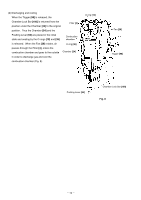
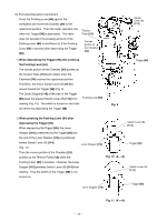
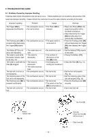
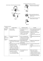
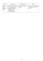
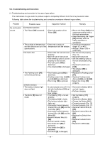
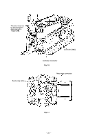
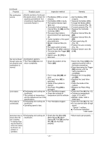
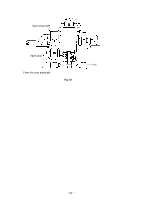
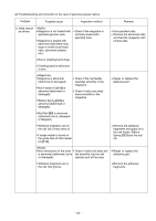
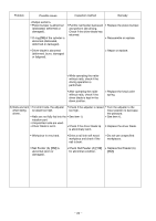
9-2. Troubleshooting and Correction (1) Troubleshooting and correction in the case of gas nailers The mechanism of a gas nailer to produce output is completely different from that of a pneumatic nailer. Following table shows the troubleshooting and correction procedures inherent in gas nailers. Problem Possible cause Inspection method Remedy No combustion occurs. (Combustion section) The Piston [39] is lowered. Check the position of the Piston [39]. The outside air temperature Check the outside air and the altitude are out of the temperature and the altitude. specifications. No fuel is fed. Check that the fuel cell is set properly. Short of fuel in the fuel cell. The metering valve is not set properly to the fuel cell. The Cell Lever [105] is deformed. The Adapter [30] is damaged. The Pushing Lever [64] cannot be pushed up. The battery indicator light does not light. The Motor [6] does not rotate. The Pushing Lever [64] is deformed. Pushing Lever Arms (A) [60] and (B) [62] are deformed. The O-ring [15] is pinched. It automatically turns off if it is left with the Battery [111] set (for Europe). Low voltage. The Battery [111] is not set properly. The Battery [111] is faulty. The battery indicator light lights red. Connection failure between Internal Wire (A) [86] and the Controller [101]. Connection failure between Internal Wire (A) [86] and the Motor [6]. Break in Internal Wire (A) [86]. The fan switch is faulty. The Switch Arm [82] is deformed. The Switch Arm [82] is deformed. The Motor [6] is damaged. Return the Piston [39] to the uppermost position with a flat-blade screwdriver. Keep depressing the Trigger [98] securely until the nailing operation is completed. Outside air temperature range: 0ûC to 40ûC Altitude: Under 1500 m (5000 feet) Set the fuel cell properly (Fig. 14). Replace the fuel cell. Set the metering valve to the fuel cell properly (Fig. 15). Replace the Cell Lever [105]. The Adapter [30] is damaged. Replace the Pushing Lever [64]. Replace Pushing Lever Arms (A) [60] and (B) [62]. Mount the O-ring [15] properly. Remove the Battery [111] and set it again. Perform charging. Set the Battery [111] properly. Replace the Battery [111]. Charge the Battery [111]. Connect properly (Fig. 16). Connect properly (Fig. 17). Replace Internal Wire (A) [86]. Replace Internal Wire (A) [86]. Replace the Switch Arm [82]. Replace the Switch Arm [82]. Replace the Motor [6]. --- 19 ---
-
 1
1 -
2
-
3
-
4
-
5
-
6
-
7
-
8
-
9
-
10
-
11
-
12
-
13
-
14
-
15
-
16
-
 17
17 -
 18
18 -
 19
19 -
 20
20 -
 21
21 -
 22
22 -
 23
23 -
 24
24 -
 25
25 -
 26
26 -
 27
27 -
28
-
29
-
30
-
31
-
32
-
33
-
34
-
35
-
36
-
37
-
38
-
39
-
40
-
41
-
42
-
43
-
44
-
45
-
46
-
47
-
48
-
49
-
50
-
51
-
52
-
53
-
54
-
55
-
56
-
57
-
58
-
59
-
60
-
61
-
62
-
63
-
64
-
65
-
66
-
67
-
68
-
69
-
70
-
71
-
72
-
73
-
74
-
75
-
76
-
77
-
78
 |
 |