Hitachi NR90GC Service Manual - Page 44
Remove the Seal Lock Hex. Socket Hd. Bolt M5 x 10
 |
UPC - 717709008533
View all Hitachi NR90GC manuals
Add to My Manuals
Save this manual to your list of manuals |
Page 44 highlights
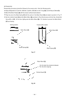
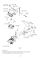
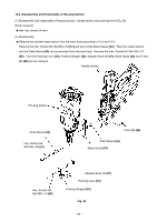
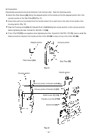
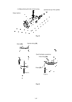
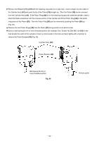
(2) Disassembly and reassembly of the housing section (Fig. 33) [Tools required] Hex. bar wrench (3 mm (0.118"), 4 mm (0.157")) Spaner (7 mm (0.276") or slender hd. pliers Roll pin puller (3 mm (0.118")) Phillips screwdriver Retaining ring puller for C-type hole Small flat-blade screwdriver (a) Disassembly Remove the Seal Lock Hex. Socket Hd. Bolt M5 x 10 [58] to remove the Cylinder plate [57]. Remove the Machine Screw M4 x 6 [33] to remove the Switch Plate [34]. Note that the Cylinder Ass'y [42] cannot be removed from the Housing Ass'y [74] without removing the Switch Plate [34]. Push the tip of the Cylinder Ass'y [42] in the Housing Ass'y [74]. Then the Cylinder Ass'y [42], chamber section, Pushing Lever Arms (A) [60] and (B) [62] can be removed from the Housing Ass'y [74] in a single unit. It is easy to remove them while pressing the side of the Housing Ass'y [74] with a hand (Fig. 34). Remove the two Pushing Lever Springs [63] with a hand. Remove the two Roll Pins D3 x 32 [25] with a roll pin puller to remove the chamber section from the Cylinder Ass'y [42]. Secure the U-Nut M4 [59] with a spanner (7 mm (0.276")) or slender hd. pliers and loosen the Hex. Socket Hd. Bolt M4 x 10 [61]. Then Pushing Lever Arms (A) [60] and (B) [62] are separated from the Pushing Lever Connector [68] and they can be removed from the Cylinder Ass'y [42]. Remove the O-ring (I.D. 66.27) [36] and two Chamber Stop Rubbers [41] with a hand. Remove the two Hex. Socket Hd. Bolts M4 x 10 [43]. Then the muffler section can be disassembled into Buffer Cover [44], Lead Valve [45] and Muffler [50]. Note that a special sealant is used for the Cylinder Ass'y [42]. Select a liquid silicon sealant capable of resisting temperatures up to 300ûC. --- 41 ---
-
 1
1 -
2
-
3
-
4
-
5
-
6
-
7
-
8
-
9
-
10
-
11
-
12
-
13
-
14
-
15
-
16
-
17
-
18
-
19
-
20
-
21
-
22
-
23
-
24
-
25
-
26
-
27
-
28
-
29
-
30
-
31
-
32
-
33
-
34
-
35
-
36
-
37
-
38
-
 39
39 -
 40
40 -
 41
41 -
 42
42 -
 43
43 -
 44
44 -
 45
45 -
 46
46 -
 47
47 -
 48
48 -
 49
49 -
50
-
51
-
52
-
53
-
54
-
55
-
56
-
57
-
58
-
59
-
60
-
61
-
62
-
63
-
64
-
65
-
66
-
67
-
68
-
69
-
70
-
71
-
72
-
73
-
74
-
75
-
76
-
77
-
78
 |
 |
