Hitachi c15fb User Manual - Page 2
E. Loosen the two M6 x 10 Hexagon Socket Hd. Set Screws - saw
 |
UPC - 717709001060
View all Hitachi c15fb manuals
Add to My Manuals
Save this manual to your list of manuals |
Page 2 highlights
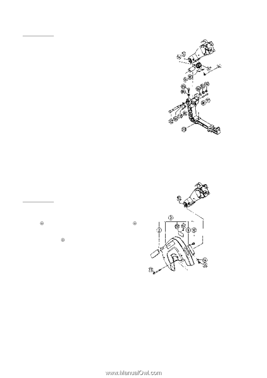
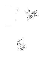
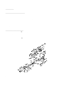
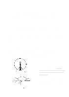
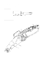
(2) Disassembly of the Spring Section and the Sleeve: Tools Required: • 17 mm Wrench, 10 mm Wrench, 6 mm Hex. Bar Wrench, and Plus Screwdriver A. This step of disassembly is dangerous and requires close attention at all times. Particular caution is necessary after releasing the fixing device (paragraph D.). B. Push the Gear Case [53] forward and down to its lowered position, and lock it in that position with the fixing device (push in the Set Pin [97] to engage the Grip [100]). C. Loosen the M10 Lock Nut [96], and screw the M10 x 40 Bolt [95] fully into the Hinge [119]. D. Being very careful as cautioned above, release the fixing device (Set Pin [97] and Grip [100]) and slowly and carefully raise the Gear Case [53]. E. Loosen the two M6 x 10 Hexagon Socket Hd. Set Screws [54], and remove the M12 Lock Nut [92] and M12 Nut [93]. Next, gently pull out the Hinge Shaft [102]. Finally, loosen the two M4 x 10 Flat Hd. Screws [65], take off the Spring Cover [68], and take out the Spring [67] and Sleeve [69]. (3) Disassembly of the Saw Cover Section: Tools Required: • Plus Screwdriver The Saw Cover Ass'y [3] can be disassembled by removing the M4 x 10 -Hd. Machine Screws [15] and four D5 x 90 -Hd. Tapping Screws [13] However, please note that to remove two of the four D5 x 90 -Hd. Tapping Screws [13] it is necessary to insert the screwdriver through the holes at either end of the Arrow Mark on the Saw Cover which indicates the rotational direction of the saw blade. Insert screwdriver through Arrow Mark holes for disassembly and reassembly. --- 2 ---
-
 1
1 -
 2
2 -
 3
3 -
 4
4 -
 5
5 -
 6
6 -
 7
7 -
 8
8 -
9
-
10
-
11
 |
 |