Hitachi c15fb User Manual - Page 3
After loosening the three M6 x 25 Flat Hd. Screws - switch
 |
UPC - 717709001060
View all Hitachi c15fb manuals
Add to My Manuals
Save this manual to your list of manuals |
Page 3 highlights
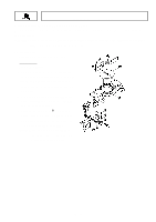
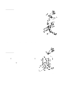
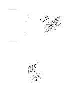
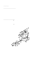
(4) Disassembly of the Switch and Handle Section: Tools Required: • Plus Screwdriver A. When only the Switch [22] must be disassembled, first loosen the two M5 x 20 -Hd. Machine Screws [18] and M5 x 16 -Hd. Machine Screw [16] which fix the Handle [20]. Then loosen the two M5 x 12 -Hd. Machine Screws [27] and two D4 x 25 Tapping Screws [35] which fix the Handle Cover [25]. The Handle [20] can then be removed from the Gear Case [53]. B. After loosening the D4 x 10 -Hd. Tapping Screws [21], the Switch [22] can be separated from the Handle [20]. (5) Disassembly of the Spindle Section and stopper Pin: Tools Required: • Plus Screwdriver, Pliers, Wooden or Plastic Hammer A. Remove the Saw Cover Ass'y [3] by following the disassembly procedures in paragraph (3), above. B. After extracting the D7 E-Type Retaining Ring [37] from the Stopper Pin [52], the Stopper Pin [52] and Gauge Spring [38] can be taken out. C. After loosening the three M6 x 25 Flat Hd. Screws [74], gently tap on the saw cover side of the Gear Case [53] to loosen and remove the Spindle Gear Ass'y [75]. --- 3 ---
-
 1
1 -
 2
2 -
 3
3 -
 4
4 -
 5
5 -
 6
6 -
 7
7 -
 8
8 -
 9
9 -
10
-
11
 |
 |
