Hitachi c15fb User Manual - Page 6
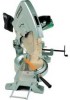
The Saw Blade could cut into the Turn Table - operating manual
 |
UPC - 717709001060
View all Hitachi c15fb manuals
Add to My Manuals
Save this manual to your list of manuals |
Page 6 highlights
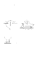
D. Finnally, ensure that the arrow mark on the Indicator [114] is properly aligned with the 0˚ setting of the Scale [89], and tighten the two M5 x 10 -Hd. Machine Screws [113]. (2) Cutting Depth Adjustment: The adjustment procedures and dimensions described below are based on the use of a 380 mm diameter Saw Blade. A. Cutting depth adjustment procedures are described in the Instruction Manual. If the M10 x 40 Bolt [95] is not properly adjusted, the following may occur: • Maximum machine cutting capacity cannot be obtained. • The Saw Blade could cut into the Turn Table [87]. B. To obtain maximum machine cutting dimensions, set the Turn Table [87] to the 0˚ setting, lower the Saw Blade, and perform adjustment with the M10 x 40 Bolt [95] so that the appropriate dimension between the surface of Vise (B) and Point A (where the Saw Blade intersects the surface of the Turn Table) is obtained, as illustrated below. Vise (B) 90˚ (0˚ Scale Setting) Check this dimension at 0˚ Scale Setting 185 mm Saw Blade 185 mm Saw Blade (Point A) (Point A) C. On completion of the above adjustment, lower the Saw Blade and ensure that it does not come in contact with the Turn Table. (3) Saw Blade Height Setting Adjustment: When the Gear Case [53] has been disassembled and then Saw Blade reassembled, adjust the M10 x 40 Bolt [95] without fail to set the Saw Blade at the most appropriate height (H) above Workpiece H the Turn Table for the operator to conveniently perform normal cutting operations. Details concerning adjustment Vise (B) procedures are listed in the Instruction Manual; study them carefully, and set the height in accordance with cutting needs. 1-4. Confirmation of Appropriate Insulation: When making leadwire connections, do not remove any more of the insulation covering than is absolutely necessary. For example, ensure there are no exposed wire cores projecting from connectors, terminals, etc. In particular, carefully confirm that there are no exposed wire cores at the terminals of the Switch. In addition, carefully avoid pinching leadwires between the Handle and Handle Cover during reassembly. --- 6 ---
-
 1
1 -
 2
2 -
 3
3 -
 4
4 -
 5
5 -
 6
6 -
 7
7 -
 8
8 -
 9
9 -
 10
10 -
 11
11
 |
 |
