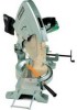
Hitachi c15fb User Manual - Page 5
Perpendicularity Adjustment of the Saw Blade or Dummy Disc and Vise B - breakdown
 |
UPC - 717709001060
View all Hitachi c15fb manuals
Add to My Manuals
Save this manual to your list of manuals |
Page 5 highlights
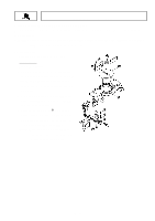
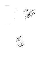
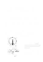
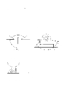
A. With the main switch turned ON, measure the insulation resistance between the plug prongs and exposed metal portions of the frame with a 500V DC Megohm Tester. The reading should be in excess of 7 megohms. B. If possible, a dielectric strength test should be conducted. With a Dielectric Withstand Voltage Tester, apply 4,000 volts between the plug prongs and exposed metal portions of the frame for one (1) minute with the main switch turned ON. Confirm that there is no "flashover" or breakdown of the insulation. C. After electrical testing has been completed, connect the plug to the power source and confirm the following: • There is no irregular noise. • Commutation of the Commutator portion is not excessive. • There is no abnormal vibration. (2) Ensure that the thickness of the vinyl tube which covers the leadwires from the Stator is in excess of 1.2 mm, and ensure that the vinyl tube completely covers the Stator leadwires all the way up to the polycarbonate portion of the Switch Handle. (3) If the M12 Nut and M12 Lock Nut on the Hinge Shaft are tightened excessively, it may interfere with the smooth movement of the Gear Case. If they are not tightened sufficiently, the Gear Case may move and vibrate on the Hinge, causing uneven cutting of the workpiece. Be very careful to ensure that the M12 Nut and M12 Lock Nut tightened properly to prevent vibration of the Gear Case, yet allow smooth movement of the Gear Case. 1-3. Assemblies Requiring Careful Adjustment: (1) Perpendicularity Adjustment of the Saw Blade (or Dummy Disc) and Vise (B): If the Hinge is disassembled from and then reassembled to the Turn Table, it is necessary to perform necessary adjustments to ensure the perpendicularity of the Saw Blade (or Dummy Disc) and Vise (B). A. Mount the D12.7 Steel Ball [117] and Spring (C) [118] onto the Hinge [119], and temporarily fix the Hinge onto the Turn Table [87] with the M10 x 65 Bolt [120] and M10 x 65 Screw (G) [124]. At this time, the Table Insert [86] and Guard [61] should be removed from the Turn Table [87]. Table Insert Mounting Groove Turn Table Position Saw Blade (or Dummy Disc) in exact center. B. Perform adjustment as necessary so that the Saw Blade (or Dummy Disc) is positioned exactly in the center of the Table Insert mounting groove, as illustrated left, and tighten the M10 x 65 Bolt [120] and M10 x 65 Screw (G) [124]. At this time, confirm without fail that the D12.7 Steel Ball [117] is properly engaged in the 0˚ setting hole in the Base Ass'y [103]. Square Vise (B) C. As illustrated, left, fit a square to the side surface of the Saw Blade (or Dummy Disc), and adjust Vise (B) as necessary to ensure it is exactly perpendicular to the Saw Blade. Then thoroughly tighten the four M10 x 40 Bolts [66]. Saw Blade (or Dummy Disc) --- 5 ---
-
 1
1 -
 2
2 -
 3
3 -
 4
4 -
 5
5 -
 6
6 -
 7
7 -
 8
8 -
 9
9 -
 10
10 -
 11
11
 |
 |
