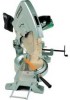
Hitachi c15fb User Manual - Page 9
Troubleshooting Guide - 15 miter saw
 |
UPC - 717709001060
View all Hitachi c15fb manuals
Add to My Manuals
Save this manual to your list of manuals |
Page 9 highlights
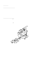
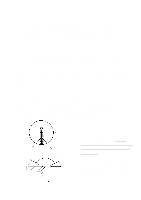
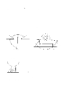
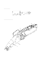
2. TROUBLESHOOTING GUIDE: The circled numbers in the descriptions below correspond to the item numbers in the Parts List and exploded assembly diagram. (All Dimensions in Millimeters) Item Phenomenon Possible Cause (s) Standard Countermeasure (s) 1. Inaccurate cutting. (Unable to obtain accurate perpendicularity of cut surface.) (Mitered joints cannot be A. Improper perpendicularity between Vise (B) [82] and the Base Ass'y [103] causes inclined bevel cutting, resulting in inaccurate angles. Within 0.1/80 (Fig. 2) Adjust or replace Vise (B) [82]. accurately aligned.) Perpendicularity Standard: 0.2/90 B. Improper perpendicularity between Saw Blade and Turn Table [87] causes Saw Blade to cut into Workpiece at inclined angle. 0.2/190 (Fig. 1) • Adjust M12 Nut [93] and M12 Lock Nut [92] to eliminate gap and vibration between Hinge [119] and Gear Case [53]. • Replace Hinge [119]. (If Hinge damaged or deformed) • Replace Gear Case [53]. (If Gear Case damaged or deformed) • Replace Turn Table [87]. (If Turn Table damaged or de- formed) Fig. 1 0.1 0.1 C. Excessive deflection of the Saw Blade. (Excessive vibration) 0.26/φ 370 (With Dummy Disc) • Replace the Saw Blade. • Replace Washer (A) [28] and/or Washer (B) [29]. Fig. 2 D. Turn Table [87] is not properly fixed with the Side Handle [116], and moves during the cutting operation. ---- Securely fix the Turn Table [87] with the Side Handle [116] and recheck after next cutting. 80 Within 0.1 Within 0.1 Fig. 3 E. Surface of Vise (B) uneven (worn or damaged) and causes uneven cutting of the workpiece. Within 0.1 Replace Vise (B) [82]. (Fig. 3) Fig. 4 F. Surface of Turn Table [87] uneven (worn or damaged) and causes uneven cutting of the workpiece. Within 0.1 Replace the Turn Table [87]. (Fig. 4) G. Excessive looseness or ex- ---- • Check for material (chips, dust, cessive tightening of the turn etc.) in the joints of the Hinge connection between the Hinge [119], Gear Case [53] and [119] and Gear Case [53] Hinge Shaft [102], and clean as which causes either vibration necessary. or irregular movement of the • Readjust M12 Nut [93] and M12 Saw Blade, and subsequent Lock Nut [92] to ensure proper uneven cutting. movement of the Gear Case [53]. H. Excessively fast cutting operation speed causes deflection of the Saw Blade, and subsequent uneven cutting. ---- • Reduce cutting operation speed. (Appropriate cutting time for a 100 mm (4") workpiece is 10 --- 15 seconds. • Use a Tungsten Carbide Tipped Saw Blade for wood or alumi- num (Code No. 959024). I. Excessive pressure is applied because of a dull Saw Blade. ---- • Resharpen or replace the Saw Blade. --- 9 ---
-
 1
1 -
2
-
3
-
 4
4 -
 5
5 -
 6
6 -
 7
7 -
 8
8 -
 9
9 -
 10
10 -
 11
11
 |
 |
