Honeywell RCWL8000A1002 User Guide - Page 7
Adjust the camera angle, Mount the Door camera
 |
UPC - 085267333979
View all Honeywell RCWL8000A1002 manuals
Add to My Manuals
Save this manual to your list of manuals |
Page 7 highlights
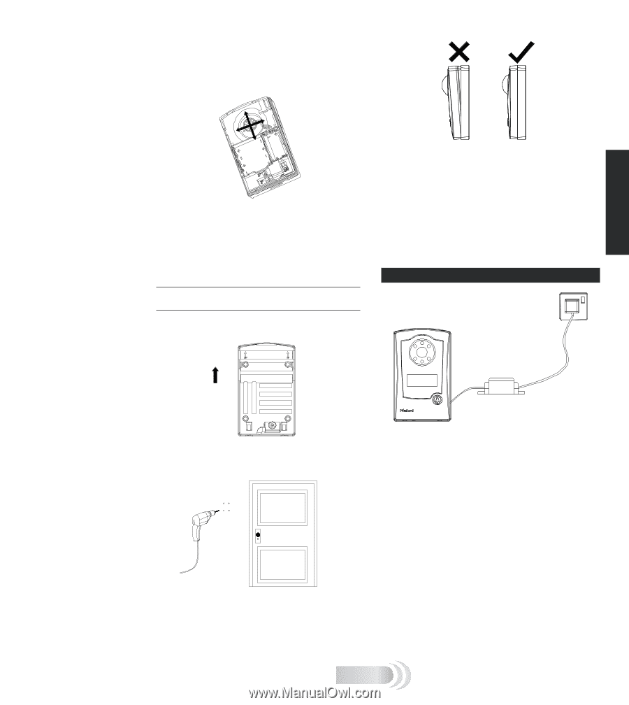
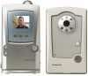
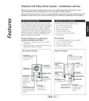
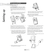
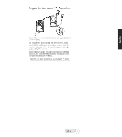
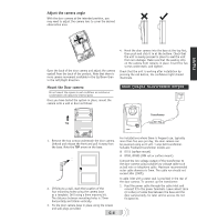
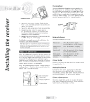
Adjust the camera angle With the door camera at the intended position, you may need to adjust the camera lens to cover the desired observation area. English Open the back of the door camera and adjust the camera eyeball from the back of the product. Note that there is more camera movement available in the Up/Down than in the Left/Right direction. 4. Hook the door camera into the base at the top first, then push and click it in at the bottom. Check that the unit is evenly pressed in place to seal the unit from rain damage. Make sure that the sealing strip on the camera front remains in place. Insert the two screws underneath, and tighten. Check that the unit is working after installation by pressing the call button, the confidence light should illuminate. Mount the Door camera Do not mount the camera in wet conditions as moisture or condensation will affect the internal parts. Once you have tested the system in place, mount the camera onto a wall or door as follows: DOOR CAMERA TRANSFORMER OPTION Transformer Top 8V / 1A 1. Remove the two screws underneath the door camera. Unhook and release the front and pull it away from the base. Note the TOP arrow on the base. 2. If fixing to a wall, mark the location of the four mounting holes using the camera base as a template. Drill using a 6mm masonry bit. The distance between mounting holes is 72mm horizontally and 92mm vertically. 3. Fix the door camera base in place using the screws and wall plugs provided. G-6 For installations where there is frequent use, typically more than five uses per day, the door camera can be powered using an 8 volt, 1 amp bell transformer. Suitable Friedland transformer models are: ■ D753 (surface mount) ■ D780, D780S (DIN rail or surface mount) Connect the low voltage output of the transformer to the door camera using suitable low voltage cable such as bell wire or telephone cable. Maximum recommended outer cable diameter is 5mm. The cable run should not exceed 30m (100ft). A cable inlet with a water seal is provided in the rear of the door camera. To connect up the transformer: 1. Feed the power cable through the cable inlet and connect it to the power terminals. Leave about 15cm (6 inches) of cable free between the base and the door camera body, for later service access. Do not fit batteries.
-
 1
1 -
 2
2 -
 3
3 -
 4
4 -
 5
5 -
 6
6 -
 7
7 -
 8
8 -
 9
9 -
 10
10 -
 11
11 -
 12
12 -
13
-
14
-
15
-
16
-
17
-
18
-
19
-
20
-
21
-
22
-
23
-
24
-
25
-
26
-
27
-
28
-
29
-
30
-
31
-
32
-
33
-
34
-
35
-
36
-
37
-
38
-
39
-
40
-
41
-
42
-
43
-
44
-
45
-
46
-
47
-
48
-
49
-
50
-
51
-
52
 |
 |