Honeywell VISTA 15P Operation Guide - Page 21
Using the AVS System with AVS Module and AVST Remote Stations - battery
 |
UPC - 781410414846
View all Honeywell VISTA 15P manuals
Add to My Manuals
Save this manual to your list of manuals |
Page 21 highlights
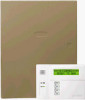
Audio Alarm Verification Connections (AVS System) Mounting and Wiring the Control Using the AVS System with AVS Module and AVST Remote Stations The AVS system provides audio alarm verification via the phone line or via AlarmNet if the GSMV module is used as the communication device. Refer to the instructions included with the AVS system for installation procedures. The following is a summary. Mounting the AVS Base Unit As shipped, the AVS Base unit board comes pre-mounted on its mounting bracket, which is designed to mount inside the control cabinet. Refer to the diagram at right. a. Position the mounting plate/PC SECURE WITH TWO (2) SELF-TAP SCREWS (SUPPLIED) board assembly in the bottom of the control's cabinet. b. Slide the mounting plate to the SYSTEM BATTERY CABINET TIE-WRAP LOOP right so that the plate's left-hand ON 1 234 ON 1 234 5 tang slides under the cabinet's tiewrap loop. c. Secure the assembly to the cabinet using the two self-tapping screws provided. TANG BENEATH MOUNTING PLATE SLIDE ASSEMBLY TO RIGHT UNTIL TANG SLIPS UNDER CABINET LOOP AVS-003-V0 BATTERY NOTE: When using a 7AH battery, mount the battery vertically on the bottom left-hand side of the cabinet, with the terminals facing down and right (negative terminal closest to the PC board bracket). Wiring the AVS to the Control The AVS Base unit board has several terminal blocks for making connections to remote stations, telephone lines, and to the control panel. The AVS base unit connects to the control's ECP terminals, with all other ECP devices connecting to the AVS base unit ECP terminals. See the diagram on the next page for specific wiring connections. DIP Switch: Set the AVS DIP switch to the appropriate address (V15P = 08; V20P = 11). IMPORTANT: The AVS should be the only ECP device connected to the control's ECP terminals. Connect all other ECP devices (keypads, expander modules, etc.) to the ECP terminals on the AVS board. Connecting an Optional GSMV Module a. If using a GSMV module for 2-way voice operation, install the module according to its instructions. NOTE: The module must be mounted within three feet of the control. b. Connect the audio cable from the GSMV module to the Audio connector on the AVS board. The audio cable is supplied with the GSMV module. c. Complete all other GSMV wiring following the instructions included with that module. The following summarizes the programming steps for AVS operation (refer to the Programming Guide for details of the AVS Quick Command options): a. Install the AVS module according to its instructions. b. Use one of the control's AVS Quick Program commands as follows : • installer code + [#] + 03: enable AVS operation without panel sounds on the AVST • installer code + [#] + 04: enable AVS operation and enable panel sounds on the AVST speaker c. Use data field ∗55 Dynamic Signaling Priority to select the desired reporting paths. 2-15
-
 1
1 -
2
-
3
-
4
-
5
-
6
-
7
-
8
-
9
-
10
-
11
-
12
-
13
-
14
-
15
-
 16
16 -
 17
17 -
 18
18 -
 19
19 -
 20
20 -
 21
21 -
 22
22 -
 23
23 -
 24
24 -
 25
25 -
 26
26 -
27
-
28
-
29
-
30
-
31
-
32
-
33
-
34
-
35
-
36
-
37
-
38
-
39
-
40
 |
 |