Honeywell VISTA 15P Operation Guide - Page 9
AC Power, Battery, and Ground Connections - panel
 |
UPC - 781410414846
View all Honeywell VISTA 15P manuals
Add to My Manuals
Save this manual to your list of manuals |
Page 9 highlights
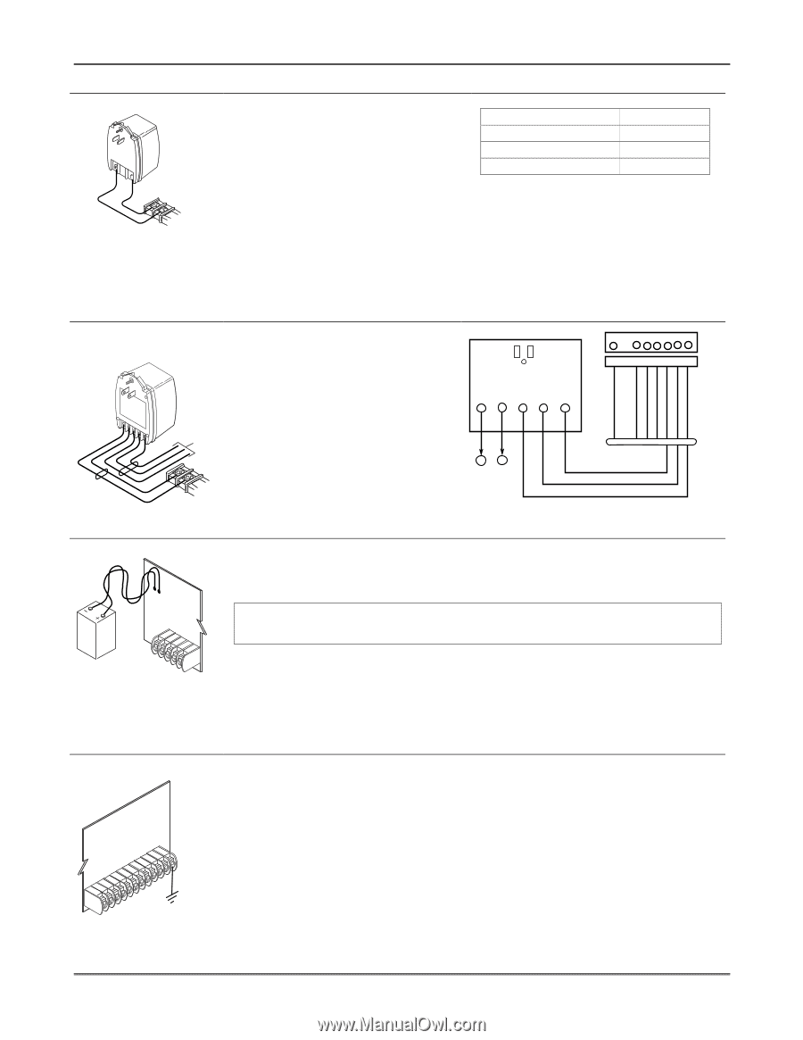
Mounting and Wiring the Control AC Power, Battery, and Ground Connections 1321 Transformer TO TERMINALS 1 AND 2 1 2 1321X10-001-V0 1361X10 Transformer (required if using Powerline Carrier devices) AC AC OSuytnpcut CSoimgnmaol n DX1a0ta TO 8-PIN CONNECTOR 1 2 TO TERMINALS 1 AND 2 Battery Connections BLACK RED 1361X10-001-V0 Connect the 1321 Transformer (1321CN in Canada) to terminals 1 and 2 on the control board. See Wire Run Chart for wire size to use. • Use caution when wiring the transformer to the control to guard against blowing the transformer fuse (the fuse is non-replaceable). Wire Run Chart Distance from control Up to 50 feet 50-100 feet 100-250 feet Wire Size # 20 # 18 # 16 • Wiring to the AC transformer must not exceed 250 feet using 16 gauge wire. The voltage reading between terminals 1 and 2 of the control must not fall below 16.5VAC or an "AC LOSS" message will be displayed. • Do not plug the transformer into the AC outlet until all wiring connections to the control are complete. As a safety precaution, always power down the control when making such connections. (BLACK) (PURPLE) (BLUE) OUTPUT 18 (GREEN) GND (-) (YELLOW) KEY +12 AUX. (ORANGE) 1. Splice one end of a 3-conductor cable to the wire ends of the SA4120XM-1 8-PIN TRIGGER CONNECTOR 1 345678 Cable. OUTPUT 17 (RED) 2. Connect the SA4120XM-1 cable plug 1361X10 TRANSFORMER to the 8-pin connector on the control (see the Summary of Connections diagram for location of the 8-pin AC AC SYNC COM DATA 1 2 3 4 5 SYNC COM DATA connector). 3. Connect the other end of the SA412OXM CABLE 3-conductor cable to the 1361X10 1 2 Transformer, as shown in Figure 4. Canadian Installations: See CONTROL BOARD TERMS. Powerline Carrier Device section for connections to the PSC04 X-10 Interface Figure 4. 1361X10 Transformer Connections and trigger pins. 1. Place the 12-volt backup battery in the cabinet. 2. After all connections to the control are completed and AC power has been applied, connect the red and black flying leads on the control board to the battery. Do not attach these leads to the battery terminals until all connections are completed. UL For UL installations and Residential fire installations, refer to the chart on page 2-2 at left for the correct battery size required to meet the mandatory standby time. batt_conn-001-V0 CONNECT FLYING LEADS AFTER AC POWER IS APPLIED Battery Saver Feature Earth Ground CONTROL BOARD 25 CONNECT PROPER EARTH GROUND IF DESIRED earth_gnd-001-V0 The battery will disconnect from the system after its voltage decreases below 9VDC. This assists the control panel in recharging the battery when AC is restored. IMPORTANT: The panel will not power up initially on battery power only. You must plug the transformer in first, and then connect the battery. • This product has been designed and laboratory-tested to ensure its resistance to damage from generally expected levels of lightning and electrical discharge, and does not normally require an earth ground. • If an earth ground is desired for additional protection in areas of severe electrical activity, terminal 25 on the control board, or the cabinet, may be used as the ground connection point. The following are examples of good earth grounds available at most installations. Metal Cold Water Pipe: Use a non-corrosive metal strap (copper is recommended) firmly secured to the pipe to which the ground lead is electrically connected and secured. AC Power Outlet Ground: Available from 3-prong, 120VAC power outlets only. To test the integrity of the ground terminal, use a 3-wire circuit tester with neon lamp indicators, such as the UL Listed Ideal Model 61-035, or equivalent, available at most electrical supply stores. 2-3
-
 1
1 -
2
-
3
-
 4
4 -
 5
5 -
 6
6 -
 7
7 -
 8
8 -
 9
9 -
 10
10 -
 11
11 -
 12
12 -
 13
13 -
 14
14 -
15
-
16
-
17
-
18
-
19
-
20
-
21
-
22
-
23
-
24
-
25
-
26
-
27
-
28
-
29
-
30
-
31
-
32
-
33
-
34
-
35
-
36
-
37
-
38
-
39
-
40
 |
 |