IBM 8862 User Manual - Page 27
hot-swappable, Option, Installation, Guide
 |
UPC - 000435172679
View all IBM 8862 manuals
Add to My Manuals
Save this manual to your list of manuals |
Page 27 highlights
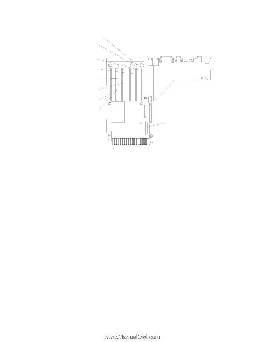
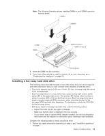
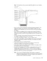
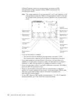
Note: The illustrations in this document might differ slightly from your hardware. Attention LED Power LED PCI slot 1 33 MHz 64-bit PCI-X slot 2 100 MHz 64-bit PCI-X slot 3 133 MHz 64-bit PCI-X slot 4 133 MHz 64-bit PCI-X slot 5 133 MHz 64-bit PCI-X slot 6 133 MHz 64-bit SCSI internal cable connector (J17) v Slot 1 is a PCI slot and is dedicated to the Remote Supervisor Adapter II. The adapter will operate in PCI mode only. The bus speed is 33 MHz only. The adapter is not hot-swappable; turn off the server when removing and installing the adapter. v Slot 2 supports hot-plugging only for an adapter with a speed of 100 MHz or higher. You can install an adapter with a speed less than 100 MHz in this slot only while the server is turned off; the bus speed will be set to the speed of the adapter. v For slots 3 through 6, the bus speed will be set to the speed of the adapter; if a PCI adapter is installed, the bus will run in PCI mode. v If you install a ServeRAID 6i adapter, it must be installed in slot 2. v If you install an IXA adapter, it must be installed in slot 3 and you must set the IXA jumper. Instructions for setting the IXA jumper are provided in the Option Installation Guide. v Each PCI/PCI-X slot is on a separate PCI bus. v Locate the documentation that comes with the adapter and follow those instructions in addition to the instructions in this chapter. v If you need to change switch settings or jumper settings on the adapter, follow the instructions that come with the adapter. v Your server scans devices and PCI-X slots to assign system resources in the following order: CD-ROM drive; disk drives; integrated Ethernet controller; integrated SCSI devices; and PCI-X slots 1, 2, 3, 4, 5, and 6. If an RXE-100 enclosure is attached to the server, the scan continues in sequence with PCI-X slots 7, 8, 9, 10, 11, 12, 13, 14, 15, 16, 17, and 18. Note: You can use the Configuration/Setup Utility program to change the sequence and have the server scan one of the first six PCI-X slots before it scans the integrated devices. You cannot change the scan sequence of the PCI-X slots in an RXE-100 enclosure. Chapter 2. Installing options 15
-
 1
1 -
2
-
3
-
4
-
5
-
6
-
7
-
8
-
9
-
10
-
11
-
12
-
13
-
14
-
15
-
16
-
17
-
18
-
19
-
20
-
21
-
 22
22 -
 23
23 -
 24
24 -
 25
25 -
 26
26 -
 27
27 -
 28
28 -
 29
29 -
 30
30 -
 31
31 -
 32
32 -
33
-
34
-
35
-
36
-
37
-
38
-
39
-
40
-
41
-
42
-
43
-
44
-
45
-
46
-
47
-
48
-
49
-
50
-
51
-
52
-
53
-
54
-
55
-
56
-
57
-
58
-
59
-
60
-
61
-
62
-
63
-
64
-
65
-
66
-
67
-
68
-
69
-
70
-
71
-
72
-
73
-
74
-
75
-
76
-
77
-
78
-
79
-
80
-
81
-
82
-
83
-
84
-
85
-
86
-
87
-
88
-
89
-
90
-
91
-
92
-
93
-
94
-
95
-
96
-
97
-
98
-
99
-
100
-
101
-
102
-
103
-
104
 |
 |