IBM 8862 User Manual - Page 35
overtighten
 |
UPC - 000435172679
View all IBM 8862 manuals
Add to My Manuals
Save this manual to your list of manuals |
Page 35 highlights
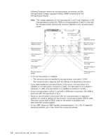
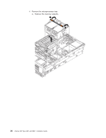
Attention: You must ensure that the locking lever on the microprocessor socket is in the fully-open position before you insert the microprocessor in the socket. Failure to do so might result in permanent damage to the microprocessor, microprocessor socket, and system board. Microprocessor Microprocessor orientation indicator Microprocessor connector Microprocessorrelease lever 8. Install the microprocessor. 9. Close the microprocessor-release lever to secure the microprocessor. Attention: v Do not disturb or contaminate the thermal material on the bottom of the new heat sink. Doing so damages its heat-conducting capability and exposes the new microprocessor to overheating. v If you need to remove the heat sink after installing it, note that the thermal material might have formed a strong bond between the heat sink and the microprocessor. Do not force the heat sink and microprocessor apart; doing so can damage the microprocessor pins. Loosening one captive screw fully before loosening the other captive screw helps break the bond between the components without damaging them. 10. Remove the heat sink from its package and remove the cover from the bottom of the heat sink. Make sure that the thermal material is still on the bottom of the heat sink. Remove the release liner and orient the heat sink above the microprocessor; then, press the heat sink into place. Press firmly on the captive screws and tighten them, alternating between screws until they are tight. Do not overtighten the screws. 11. If you installed the microprocessor in connector 3 or 4, install the VRM in the applicable microprocessor VRM connector (VRM connector 3 for microprocessor 3, VRM connector 4 for microprocessor 4). See the illustration on page 18 for the location of the VRM connectors. 12. Reinstall the microprocessor tray in the server: a. Make sure the microprocessor-tray release latch is open; then, push the microprocessor tray into the server. b. Close the tray levers and make sure they are securely latched. c. Press the microprocessor-tray release latch down. d. Reinstall the fans and memory cassette in the server. Chapter 2. Installing options 23
-
 1
1 -
2
-
3
-
4
-
5
-
6
-
7
-
8
-
9
-
10
-
11
-
12
-
13
-
14
-
15
-
16
-
17
-
18
-
19
-
20
-
21
-
22
-
23
-
24
-
25
-
26
-
27
-
28
-
29
-
 30
30 -
 31
31 -
 32
32 -
 33
33 -
 34
34 -
 35
35 -
 36
36 -
 37
37 -
 38
38 -
 39
39 -
 40
40 -
41
-
42
-
43
-
44
-
45
-
46
-
47
-
48
-
49
-
50
-
51
-
52
-
53
-
54
-
55
-
56
-
57
-
58
-
59
-
60
-
61
-
62
-
63
-
64
-
65
-
66
-
67
-
68
-
69
-
70
-
71
-
72
-
73
-
74
-
75
-
76
-
77
-
78
-
79
-
80
-
81
-
82
-
83
-
84
-
85
-
86
-
87
-
88
-
89
-
90
-
91
-
92
-
93
-
94
-
95
-
96
-
97
-
98
-
99
-
100
-
101
-
102
-
103
-
104
 |
 |
