Icom IC-F70 / F80 Instruction Manual - Page 8
Panel Description
 |
View all Icom IC-F70 / F80 manuals
Add to My Manuals
Save this manual to your list of manuals |
Page 8 highlights
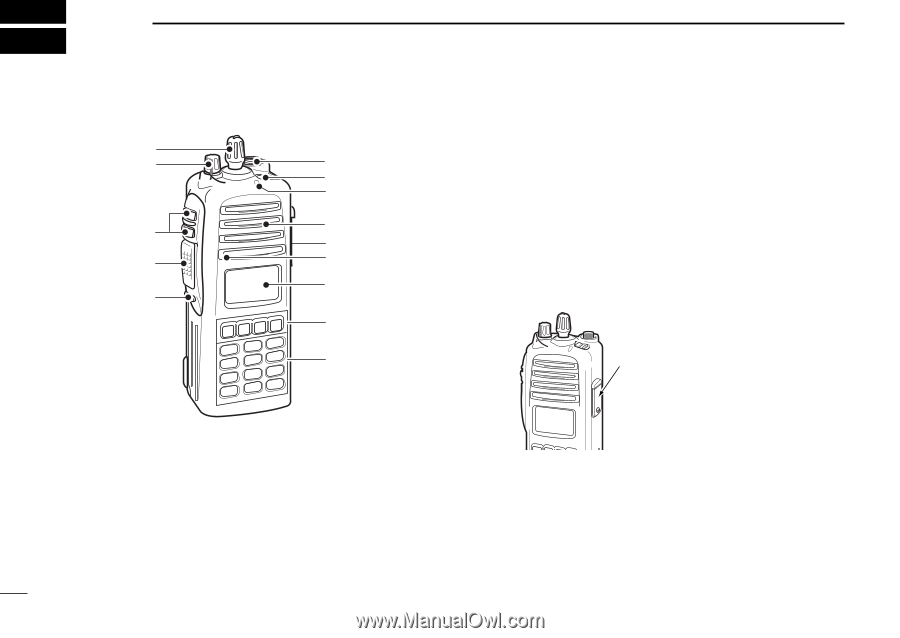
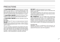
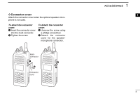
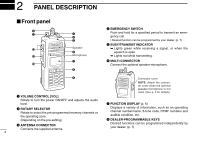
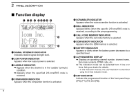
2 PANEL DESCRIPTION I Front panel w q !2 !1 !0 e r t Speaker y Microphone u i r EMERGENCY SWITCH Push and hold for a specified period to transmit an emergency call. • Desired function can be programmed by your dealer. (p. 7) t BUSY/TRANSMIT INDICATOR ➥ Lights green while receiving a signal, or when the squelch is open. ➥ Lights red while transmitting. y MULTI-CONNECTOR Connect the optional speaker-microphone. o Connector cover NOTE: Attach the connector cover when the optional speaker-microphone is not used. (See p. 3 for details) q VOLUME CONTROL [VOL] Rotate to turn the power ON/OFF and adjusts the audio level. u FUNCTION DISPLAY (p. 6) w ROTARY SELECTOR Rotate to select the pre-programmed memory channels or the operating zone. Displays a variety of information, such as an operating channel number/name, 5-tone code, DTMF numbers and audible condition, etc. (Depending on the pre-setting) i DEALER-PROGRAMMABLE KEYS e ANTENNA CONNECTOR Connects the supplied antenna. Desired functions can be programmed independently by your dealer. (p. 7) 4
-
 1
1 -
2
-
 3
3 -
 4
4 -
 5
5 -
 6
6 -
 7
7 -
 8
8 -
 9
9 -
 10
10 -
 11
11 -
 12
12 -
 13
13 -
14
-
15
-
16
-
17
-
18
-
19
-
20
-
21
-
22
-
23
-
24
-
25
-
26
-
27
-
28
-
29
-
30
-
31
-
32
-
33
-
34
-
35
-
36
-
37
-
38
-
39
-
40
-
41
-
42
-
43
-
44
-
45
-
46
-
47
-
48
 |
 |