Icom IC-M36 Service Manual - Page 4
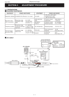
Frequency Adjustments, Adjustment, Transceiver's, Condition, Operation, Value, Jig Cable - antenna
 |
View all Icom IC-M36 manuals
Add to My Manuals
Save this manual to your list of manuals |
Page 4 highlights
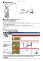
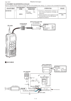
Feb. 2012 (Replacement page) 5-2 FREQUENCY ADJUSTMENTS Select an adjustment item using keys, then set to the specified value using keys on the connected PC's keyboard. ADJUSTMENT ADJUSTMENT ITEM TRANSCEIVER'S CONDITION OPERATION VALUE PLL LOCK 1 VOLTAGE (VERIFICATION) 2 [LVIN] (I/O check window) • CH. : 16 • Receiving • CH. : 16 • TX power : Low • Transmitting 1) Connect an RF power meter (or a Dummy load) to the antenna connector. 2) Verify that the lock voltage is in the specified range on the "I/O check window" (see the illust below). 1.9-2.9 V (Verify) 1.7-2.8 V (Verify) REFERENCE FREQUENCY 1 • CH. : 16 • TX power : Low [Ref. Freq.] • Transmitting 1) Connect an RF power meter (or a Dummy load) to the antenna connector. 2) Loose couple a Frequency counter to 156.8000 MHz the antenna connector. 3) Adjust the TX frequency. (Loose Coupling) RF POWER METER (10 W/50 Ω) JIG cable FREQUENCY COUNTER (0.1-300 MHz) I/O CHECK WINDOW LOCK VOLTAGE Click to reload the parameter (The values shown in the above screen are example only. Each transceiver has their own values.) 5 - 3
-
 1
1 -
 2
2 -
 3
3 -
 4
4 -
 5
5 -
 6
6 -
 7
7 -
 8
8 -
 9
9 -
 10
10 -
11
-
12
-
13
-
14
-
15
-
16
-
17
-
18
-
19
-
20
-
21
-
22
-
23
-
24
-
25
-
26
-
27
-
28
-
29
-
30
-
31
-
32
-
33
-
34
-
35
-
36
-
37
-
38
-
39
-
40
-
41
 |
 |
