Icom IC-M36 Service Manual - Page 5
Jig Cable, Adjustment, Transceiver's, Condition, Operation, Value, 4 Transmit Adjustments Continued
 |
View all Icom IC-M36 manuals
Add to My Manuals
Save this manual to your list of manuals |
Page 5 highlights
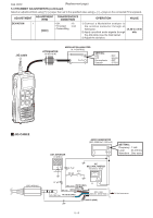
Feb. 2012 (Replacement page) 5-4 TRANSMIT ADJUSTMENTS (continued) Select an adjustment item using keys, then set to the specified value using keys on the connected PC's keyboard. ADJUSTMENT ADJUSTMENT ITEM TRANSCEIVER'S CONDITION DEVIATION 1 • CH. : 16 • TX power : Low [MOD] • Transmitting OPERATION VALUE 1) Connect a Modulation analyzer to the antenna connector through an Attenuator. ±4.30 to ±4.40 2) Apply specified audio signals through kHz the JIG cable. (see the illust below). 3) Adjust the deviation. JIG cable ATTENUATOR (30 dB/10 W) MODULATION ANALYZER (0.1-300 MHz) SETTING; HPF LPF De-emphasis Detector : OFF : 20 kHz : OFF : (P-P)/2 JIG CABLE OPC-478/UC EXT. SPEAKER (1 W/8 Ω) AUDIO GENERATOR (300-3000 Hz/1-500 mV) +− SETTING; Frequency : 1 kHz Level : 25 mVrms Waveform : Sine wave AC −+ 4.7 µF MILLIVOLT METER (10 mV to 10 V) PTT 33 kΩ + + 47 µF (MIC line) WHITE (MIC) (SP line) RED (AFOUT) (CLONE line) BLUE (CLONE) +− OPC-1655 (Parts No.: 8900016330) SHIELD (GND) To the transceiver 5 - 6
-
 1
1 -
 2
2 -
 3
3 -
 4
4 -
 5
5 -
 6
6 -
 7
7 -
 8
8 -
 9
9 -
 10
10 -
 11
11 -
12
-
13
-
14
-
15
-
16
-
17
-
18
-
19
-
20
-
21
-
22
-
23
-
24
-
25
-
26
-
27
-
28
-
29
-
30
-
31
-
32
-
33
-
34
-
35
-
36
-
37
-
38
-
39
-
40
-
41
 |
 |
