Image Fitness 4.0smith Machinekit English Manual - Page 10
Locknuts
 |
View all Image Fitness 4.0smith Machinekit manuals
Add to My Manuals
Save this manual to your list of manuals |
Page 10 highlights
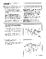
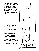
13. Press two 1" Round Inner Caps (12) into the Top Frame (24). Press two 2" x 2 3/4" Inner Caps (66) into the Top Frame. Insert the brackets on the Top Frame (24) into the tops of the Barbell Uprights (38, 41). Attach each Barbell Upright to the Top Frame with an M10 x 65mm Bolt (7) and an M10 Nylon Locknut (1). Attach each Weight Upright (42) to the Top Frame (24) with two M10 x 90mm Bolts (9) and two M10 Washers (6). It may be necessary to twist the Weight Uprights slightly to insert the Bolts. See step 11. Tighten the four M10 Nylon Locknuts (1) used in step 11. 13 24 12 9 1-• 41 66 7 42 /; 38 • 2 • 0 9 6 66 42 0 0 0 C 14. Lubricate the indicated post on the Top Frame (24). Attach an Upper Pulley Bracket (28) to the post on the Top Frame with an M12 Nylon Locknut (60). The Pulley Bracket must be oriented so that the welded stop is on top. See the Inset drawing to identify the Upper Pulley Bracket. Lubricate the indicated post on the Right Base (26). Attach a Lower Pulley Bracket (29) to the post on Left Base with an M12 Nylon Locknut (60). The Pulley Bracket must be oriented so that the welded stop is on the bottom. See the inset drawing to Identify the Lower Pulley Bracket. Attach an Upper Pulley Bracket (28) and a Lower Pulley Bracket (29) to the other side in the same manner. 14 C 24 Lubricate • Welded Stop 28 0 28 C or C 29 6 26 29 Welded Stop Lubricate Lower Pulley Upper Pulley Bracket Bracket Welded Stop O Welded Stop 10
-
 1
1 -
2
-
3
-
4
-
 5
5 -
 6
6 -
 7
7 -
 8
8 -
 9
9 -
 10
10 -
 11
11 -
 12
12 -
 13
13 -
 14
14 -
 15
15 -
16
-
17
-
18
-
19
-
20
-
21
-
22
 |
 |
