Image Fitness 4.0smith Machinekit English Manual - Page 11
tightened.
 |
View all Image Fitness 4.0smith Machinekit manuals
Add to My Manuals
Save this manual to your list of manuals |
Page 11 highlights
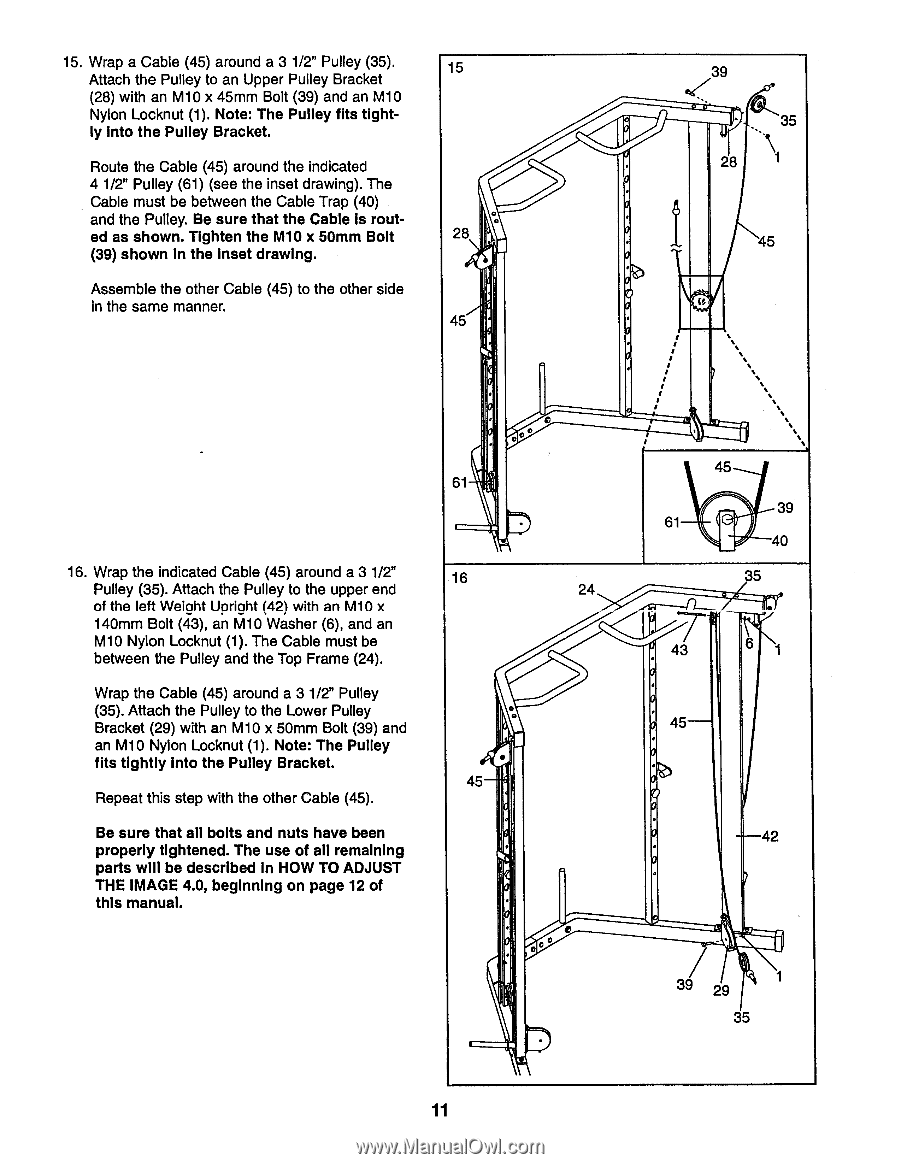
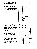
15. Wrap a Cable (45) around a 3 1/2" Pulley (35). Attach the Pulley to an Upper Pulley Bracket (28) with an M10 x 45mm Bolt (39) and an M10 Nylon Locknut (1). Note: The Pulley fits tightly Into the Pulley Bracket. Route the Cable (45) around the indicated 4 1/2" Pulley (61) (see the inset drawing). The Cable must be between the Cable Trap (40) and the Pulley. Be sure that the Cable Is routed as shown. Tighten the M10 x 50mm Bolt (39) shown in the Inset drawing. Assemble the other Cable (45) to the other side in the same manner. 15 C 28 45 39 35 28 1 45 (0 0° 61 16. Wrap the indicated Cable (45) around a 3 1/2" Pulley (35). Attach the Pulley to the upper end of the left Weight Uoriaht (42) with an M10 x 140mm Bolt (43), an M10 Washer (6), and an M10 Nylon Locknut (1). The Cable must be between the Pulley and the Top Frame (24). Wrap the Cable (45) around a 3 1/2" Pulley (35). Attach the Pulley to the Lower Pulley Bracket (29) with an M10 x 50mm Bolt (39) and an M10 Nylon Locknut (1). Note: The Pulley fits tightly into the Pulley Bracket. Repeat this step with the other Cable (45). Be sure that all bolts and nuts have been properly tightened. The use of all remaining parts will be described in HOW TO ADJUST THE IMAGE 4.0, beginning on page 12 of this manual. 16 45 24 C 45 39 61 40 35 43 6 45 42 39 29 35 11
-
 1
1 -
2
-
3
-
4
-
5
-
 6
6 -
 7
7 -
 8
8 -
 9
9 -
 10
10 -
 11
11 -
 12
12 -
 13
13 -
 14
14 -
 15
15 -
 16
16 -
17
-
18
-
19
-
20
-
21
-
22
 |
 |