Image Fitness 4.0smith Machinekit English Manual - Page 5
Assembly
 |
View all Image Fitness 4.0smith Machinekit manuals
Add to My Manuals
Save this manual to your list of manuals |
Page 5 highlights
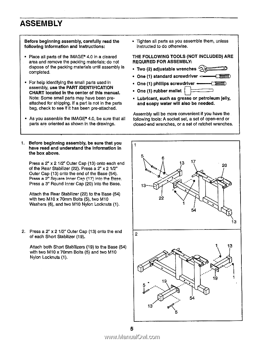
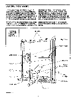
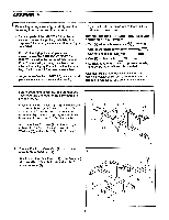
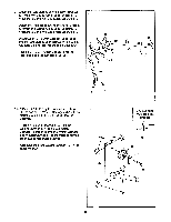
ASSEMBLY Before beginning assembly, carefully read the following information and Instructions: • Tighten all parts as you assemble them, unless instructed to do otherwise. • Place all parts of the IMAGE® 4.0 in a cleared area and remove the packing materials; do not dispose of the packing materials until assembly is completed. • For help identifying the small parts used in assembly, use the PART IDENTIFICATION CHART located In the center of this manual. Note: Some small parts may have been preattached for shipping. If a part is not in the parts bag, check to see if it has been pre-attached. • As you assemble the IMAGE® 4.0, be sure that all parts are oriented as shown in the drawings. THE FOLLOWING TOOLS (NOT INCLUDED) ARE REQUIRED FOR ASSEMBLY: • Two (2) adjustable wrenches • One (1) standard screwdriver • One (1) phIllips screwdriver • One (1) rubber mallet 7 • Lubricant, such as grease or petroleum jelly, and soapy water will also be needed. Assembly will be more convenient if you have the following tools: A socket set, a set of open-end or closed-end wrenches, or a set of ratchet wrenches. 1. Before beginning assembly, be sure that you have read and understand the Information in the box above. Press a 2" x 2 1/2" Outer Cap (13) onto each end of the Rear Stabilizer (22). Press a 2" x 2 1/2" Outer Cap (13) onto the end of the Base (54). Press a 2" Square Inner CRT (17) into the Rase. Press a 3" Round Inner Cap (20) into the Base. Attach the Rear Stabilizer (22) to the Base (54) with two M10 x 70mm Bolts (5), two M10 Washers (6), and two M10 Nylon Locknuts (1). 1 5 13 6 13 17 • 22 20 0 • 2. Press a 2" x 2 1/2" Outer Cap (13) onto the end of each Short Stabilizer (19). 2 Attach both Short Stabilizers (19) to the Base (54) with two M10 x 70mm Bolts (5) and two M10 Nylon Locknuts (1). • 19 0 13 5 13 13 0 0 0 0 19 54 5
-
 1
1 -
 2
2 -
 3
3 -
 4
4 -
 5
5 -
 6
6 -
 7
7 -
 8
8 -
 9
9 -
 10
10 -
 11
11 -
12
-
13
-
14
-
15
-
16
-
17
-
18
-
19
-
20
-
21
-
22
 |
 |