Insignia IS-NXT10232 User Manual (English) - Page 7
Getting to know your, system - subwoofer
 |
View all Insignia IS-NXT10232 manuals
Add to My Manuals
Save this manual to your list of manuals |
Page 7 highlights
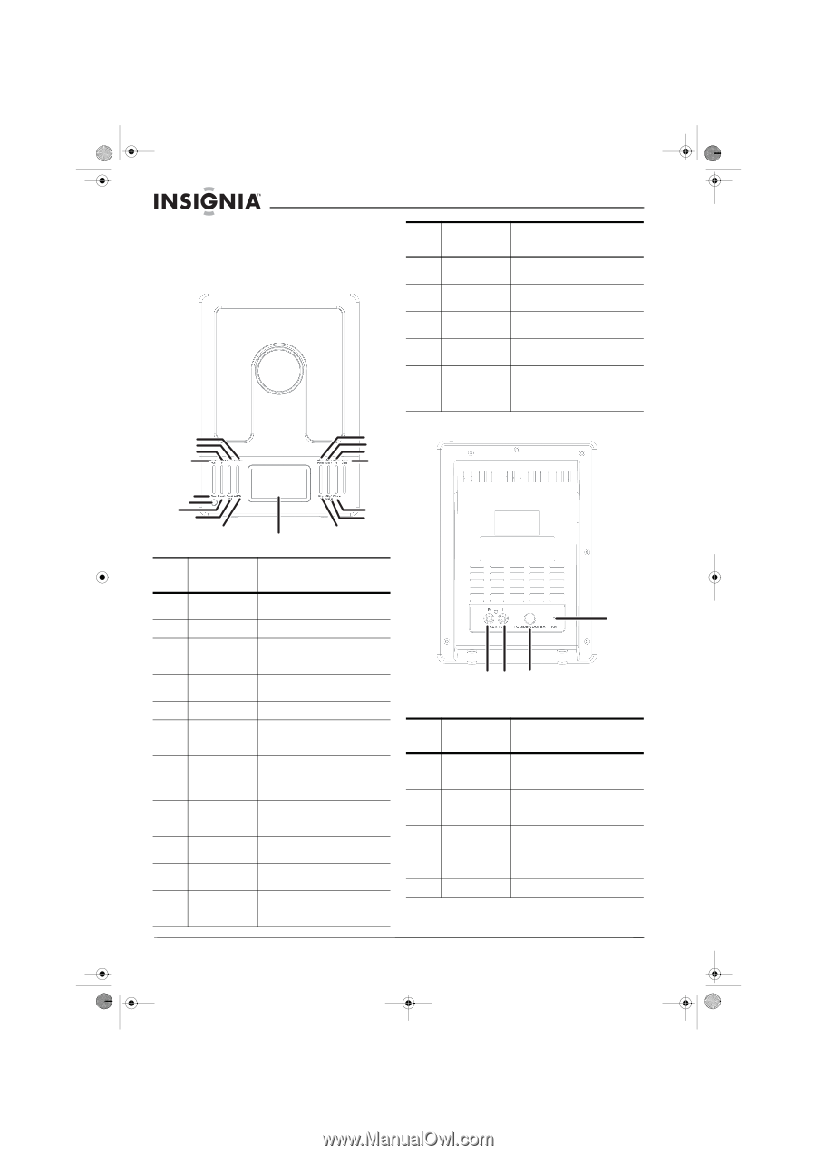
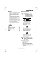
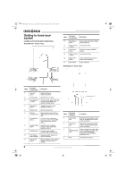
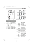
NXT Designer shelf system - combined.fm Page 6 Wednesday, July 6, 2005 9:04 AM Getting to know your system Location of controls and connections TUNER/CD UNIT - FRONT PANEL 1 11 2 12 3 13 4 14 IS-NXT10232 Designer shelf system Item Control/ connection Function 12 Skip/Tune >> Goes to the next track or higher button tuner frequency. 13 Digital volume Increases volume + button 14 Open/close Opens and closes CD/MP3 button drawer. 15 Digital volume Decreases volume - button 16 Skip/Tune CD>Aux) 2 Timer button Sets the turn-on timer. 3 Preset/Album In Tuner mode, selects the next + button preset. Playing MP3 discs, selects the next album. 4 Standby/On Toggles the system from button Standby mode to on. 5 Sleep button Sets the sleep timer. 6 Remote Receives the remote control control sensor signal from the remote control unit. 7 Preset/Album - In Tuner mode, selects the button previous preset. Playing MP3 discs, selects the previous album. 8 Clock/Program Sets the clock, programs button presets, and programmed playback options. 9 AM/FM button In Tuner mode, toggles between AM and FM bands. 10 LCD display Displays system status and with backlight other information. 11 Play/Pause Begins playback, then toggles button between Play and Pause modes. 4 12 3 Item Control/ Indicator Function 1 AUX IN (R) Attach the right speaker output jack from an outside sound source to this connector. 2 AUX IN (L) Attach the left speaker output jack from an outside sound source to this connector. 3 TO Attach one end of a 9-pin cable SUBWOOFER to this connector and the other jack end to the FROM MAIN connector on the Amplifier/ Subwoofer unit. 4 ANT The FM wire antenna. 6 www.insignia-products.com
-
 1
1 -
 2
2 -
 3
3 -
 4
4 -
 5
5 -
 6
6 -
 7
7 -
 8
8 -
 9
9 -
 10
10 -
 11
11 -
 12
12 -
13
-
14
-
15
-
16
-
17
-
18
-
19
 |
 |