Intel BLKDG43NB Product Specification - Page 48
Add-in Card Connectors, 2.2.3, Auxiliary Front Panel Power/Sleep LED Header
 |
UPC - 735858201773
View all Intel BLKDG43NB manuals
Add to My Manuals
Save this manual to your list of manuals |
Page 48 highlights
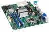
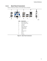
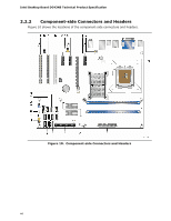
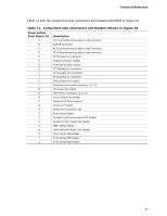
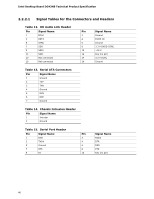
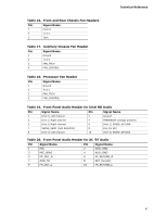
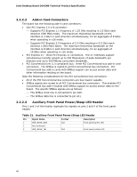
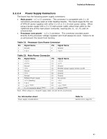
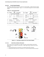
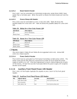
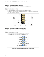
Intel Desktop Board DG43NB Technical Product Specification 2.2.2.2 Add-in Card Connectors The board has the following add-in card connectors: • One PCI Express 2.0 x16 connector: ⎯ Supports PCI Express 1.1 frequency of 1.25 GHz resulting in 2.5 Gb/s each direction (500 MB/s total). The maximum theoretical bandwidth on the interface is 4 GB/s in each direction simultaneously, for an aggregate of 8 GB/s when operating in x16 mode. ⎯ Supports PCI Express 2.0 frequency of 2.5 GHz resulting in 5.0 Gb/s each direction (1000 MB/s total). The maximum theoretical bandwidth on the interface is 8 GB/s in each direction simultaneously, for an aggregate of 16 GB/s when operating in x16 mode. • PCI Express x1: three PCI Express x1 connectors. The x1 interfaces support simultaneous transfer speeds up to 250 Mbytes/sec of peak bandwidth per direction and up to 500 MB/sec concurrent bandwidth. • PCI Conventional (rev 2.3 compliant) bus: three PCI Conventional bus add-in card connectors. The SMBus is routed to all PCI Conventional bus connectors. PCI Conventional bus add-in cards with SMBus support can access sensor data and other information residing on the board. Note the following considerations for the PCI Conventional bus connectors: • All of the PCI Conventional bus connectors are bus master capable. • SMBus signals are routed to all PCI Conventional bus connectors. This enables PCI Conventional bus add-in boards with SMBus support to access sensor data on the board. The specific SMBus signals are as follows: ⎯ The SMBus clock line is connected to pin A40. ⎯ The SMBus data line is connected to pin A41. 2.2.2.3 Auxiliary Front Panel Power/Sleep LED Header Pins 1 and 3 of this header duplicate the signals on pins 2 and 4 of the front panel header. Table 21. Auxiliary Front Panel Power/Sleep LED Header Pin Signal Name 1 HDR_BLNK_GRN 2 Not connected 3 HDR_BLNK_YEL In/Out Out Out Description Front panel green LED Front panel yellow LED 48
-
 1
1 -
2
-
3
-
4
-
5
-
6
-
7
-
8
-
9
-
10
-
11
-
12
-
13
-
14
-
15
-
16
-
17
-
18
-
19
-
20
-
21
-
22
-
23
-
24
-
25
-
26
-
27
-
28
-
29
-
30
-
31
-
32
-
33
-
34
-
35
-
36
-
37
-
38
-
39
-
40
-
41
-
42
-
 43
43 -
 44
44 -
 45
45 -
 46
46 -
 47
47 -
 48
48 -
 49
49 -
 50
50 -
 51
51 -
 52
52 -
 53
53 -
54
-
55
-
56
-
57
-
58
-
59
-
60
-
61
-
62
-
63
-
64
-
65
-
66
-
67
-
68
-
69
-
70
-
71
-
72
-
73
-
74
-
75
-
76
-
77
-
78
-
79
-
80
-
81
-
82
-
83
-
84
-
85
-
86
-
87
-
88
 |
 |